2026 UPDATE: On 10/20/2024 I gave a virtual presentation to the Potomac Division of the NMRA on upgrading the Proto 2000 GP7/9 three different ways. I go over this installation method as well as a couple other ideas. Check it out!
My friend, Tom Matty, who models the Thomas Sub of the Western Maryland Ry, a very skilled and talented modeler, offered to do a writeup of how he re-motors an old Proto2000 GP7/GP9 with a much higher quality Kato drive. It involves milling the frame, fitting the motor, linkages and worm gears and then installing your favorite flavor of DCC/sound. (we won’t cover the DCC installation here today). Tom gave me permission to post his process on the blog so I figured I’d share it with everyone who may be interested in this fantastic upgrade.
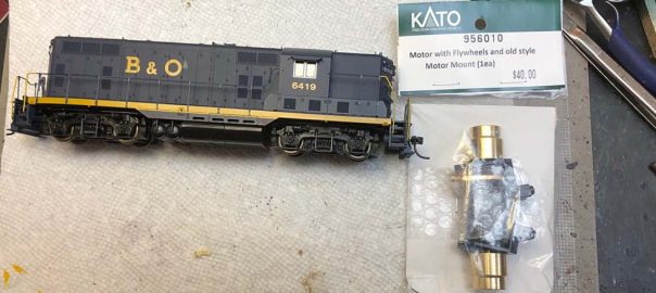
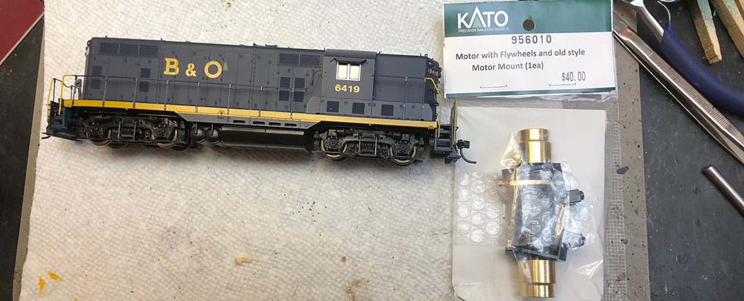
Parts needed:
1x Kato 956010 Motor with Flywheels and old style Motor Mount (1ea)
1x Athearn ATH90116 HO Dog Bone .805” F7A/B/FP7 Rear, 6 per pack
2x Athearn ATH34128 HO Worm Assembly, High Performance, 1 per pack
Photo from 2018. Not much has changed with it since then.
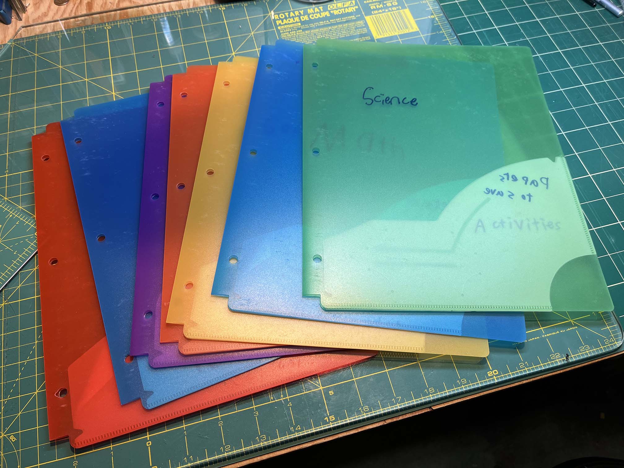
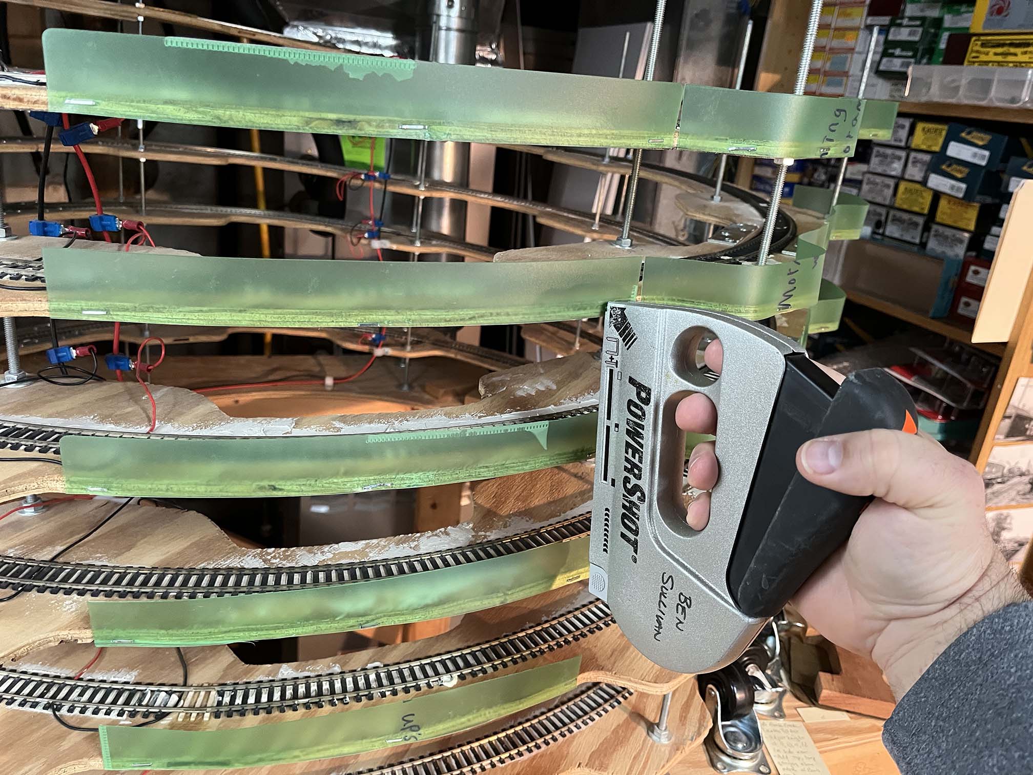
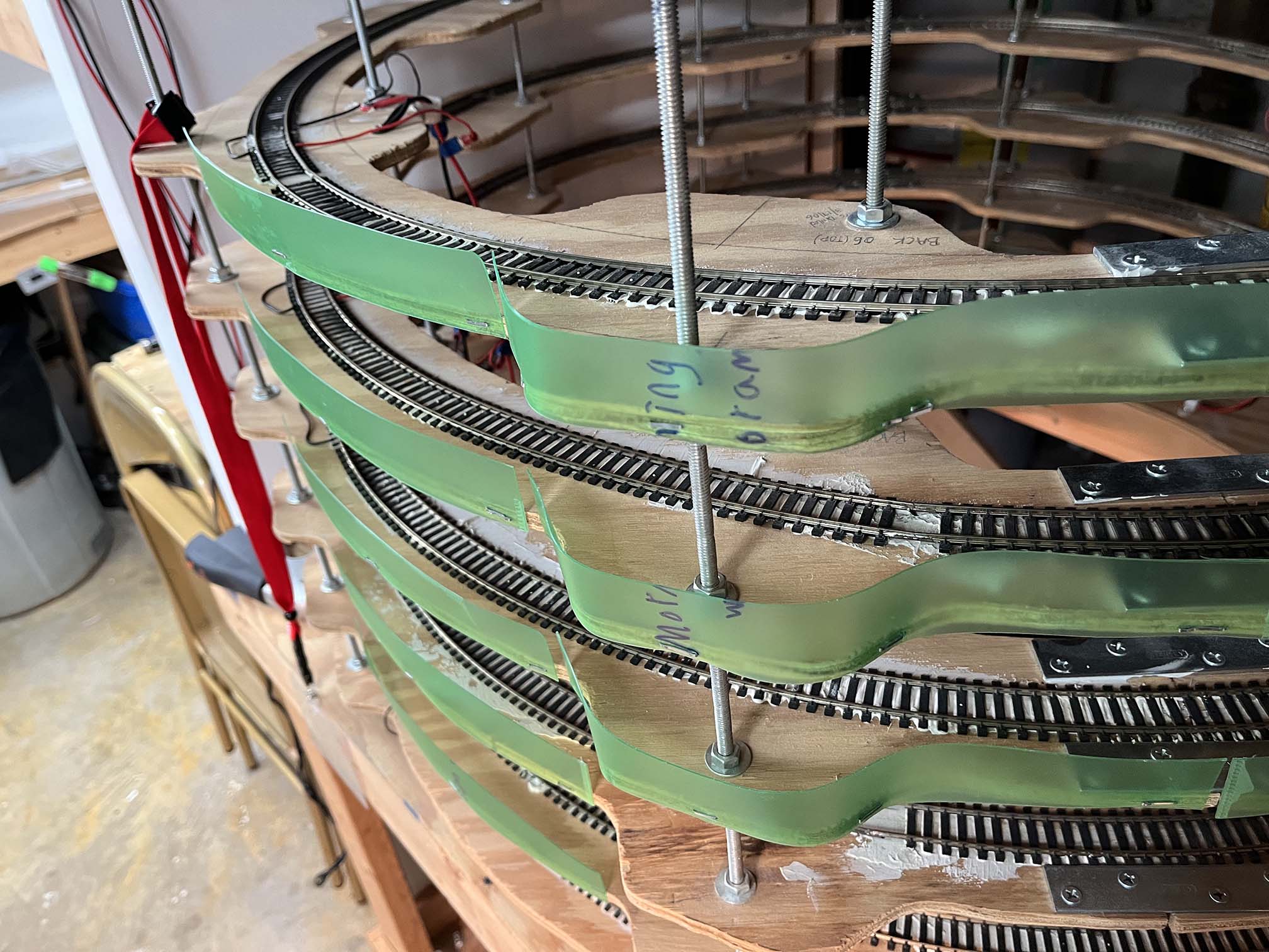
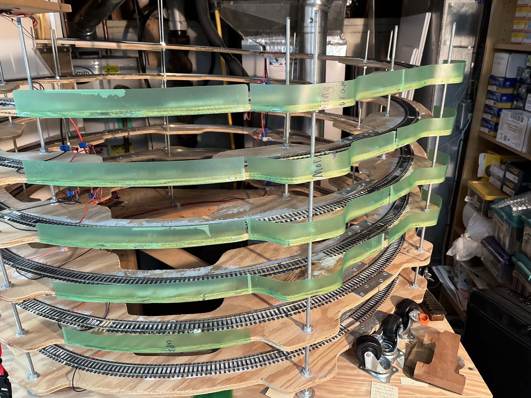
As you may or may not know, I have a helix to connect the upper and lower decks of my Georgetown Branch layout. I built the helix ages ago, back in 2003 for my previous layout. It was designed to fit below a set of stairs and as such is relatively tight, with 19.5″ radius curves and a 2.9% grade. (yikes!) Thankfully I mostly run small B+B locomotives! One thing that is lacking is any sort of protection for the trains as they traverse the helix from falling off the edge and cascading to the floor. I thought about cardboard or mat board strips but decided against them as I didn’t like the idea that they would crease or break if I had to reach in to re-rail a train. I have been kicking this idea around for ages and recently had the idea of using polypropylene folders. These are the flexible-yet-stiff plastic folders you find in a lot of school binders. When I was cleaning out a supply cabinet, I found a stash of old folders from my son’s grade school days. Perfect. So I got around to testing this out.
A nice stash of folders to slice up. I’ve got the entire outside and inside of the helix to wrap, so I will need several.
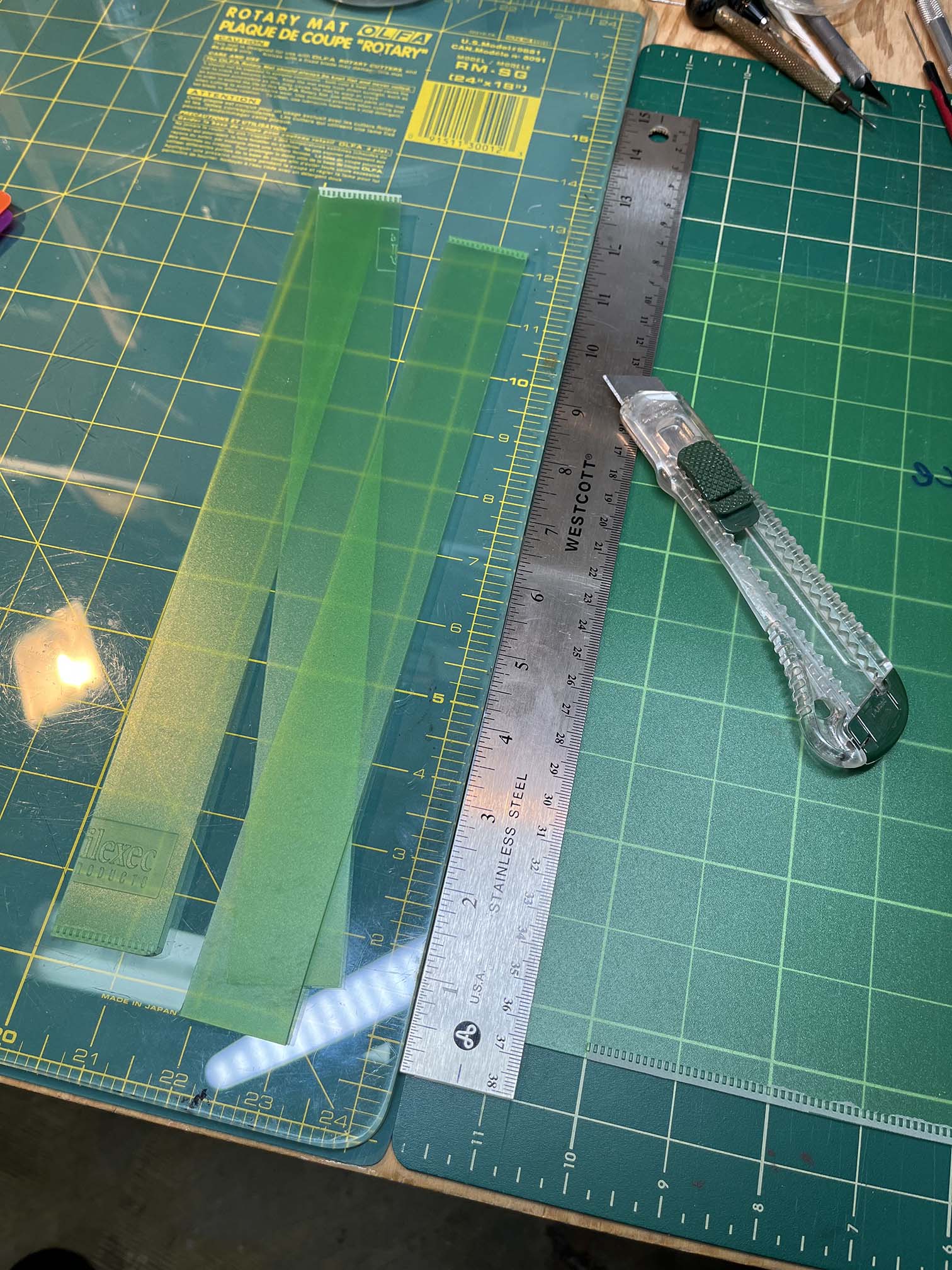
I first remove the inner folder piece (seen in the photo above as a lighter green) and then set the edge of the folder against a sheet of glass and lay my steel ruler down atop it. I then score until the sheet is cut through.
Next, lay the strips on the side of the roadbed, keeping it parallel to the bottom, and use a staple gun to fasten to the plywood.
Some of the staples will not go in all the way and I tapped them in with a hammer. Occasionally I would miss and have to remove the staple with a screwdriver and try again. I really like the way this is turning out.
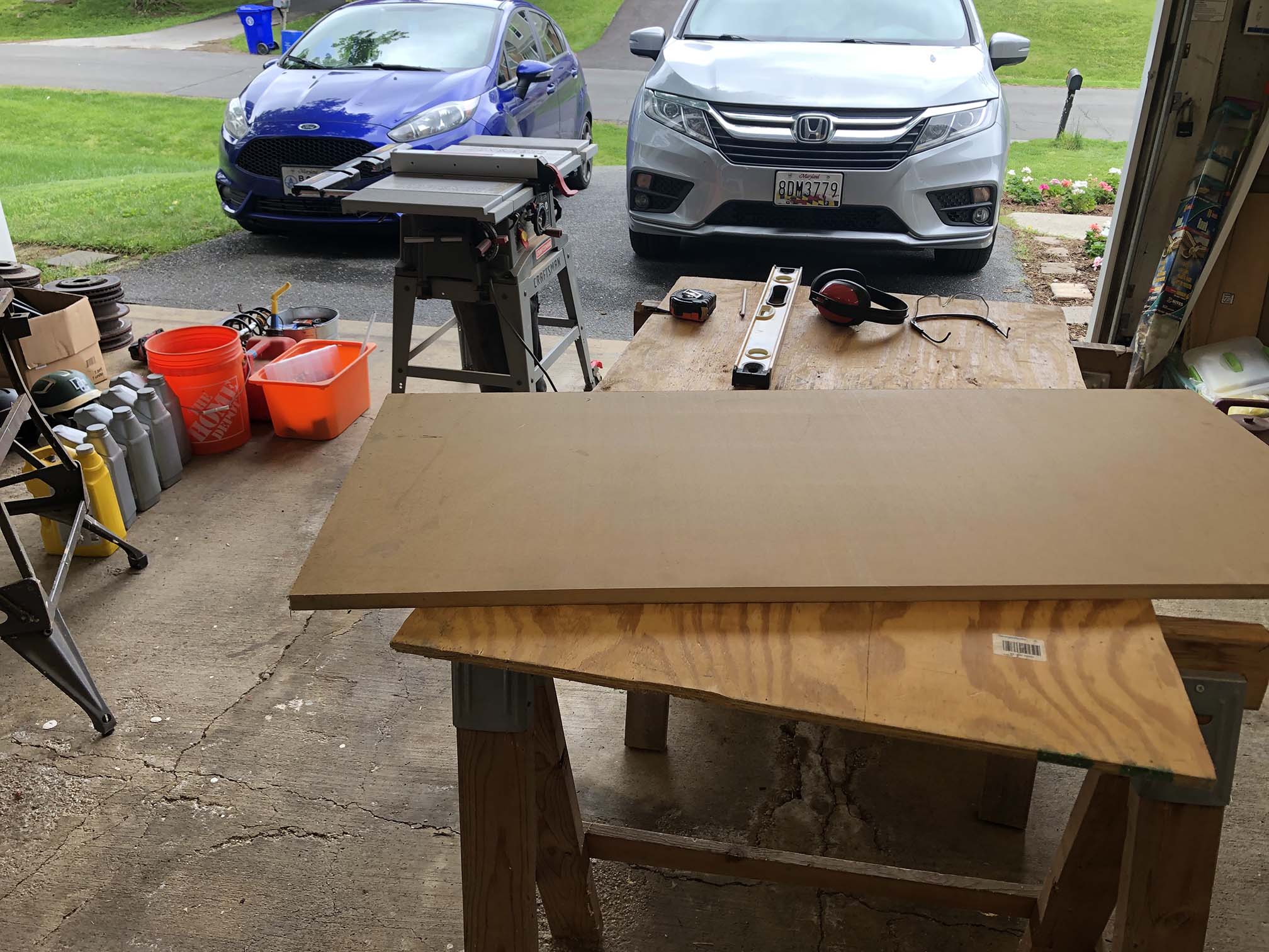
Had picked up some 1/4″ MDF a year or so ago, and this 3/4″ MDF was gifted to us. Ripping everything took a few hours to complete.
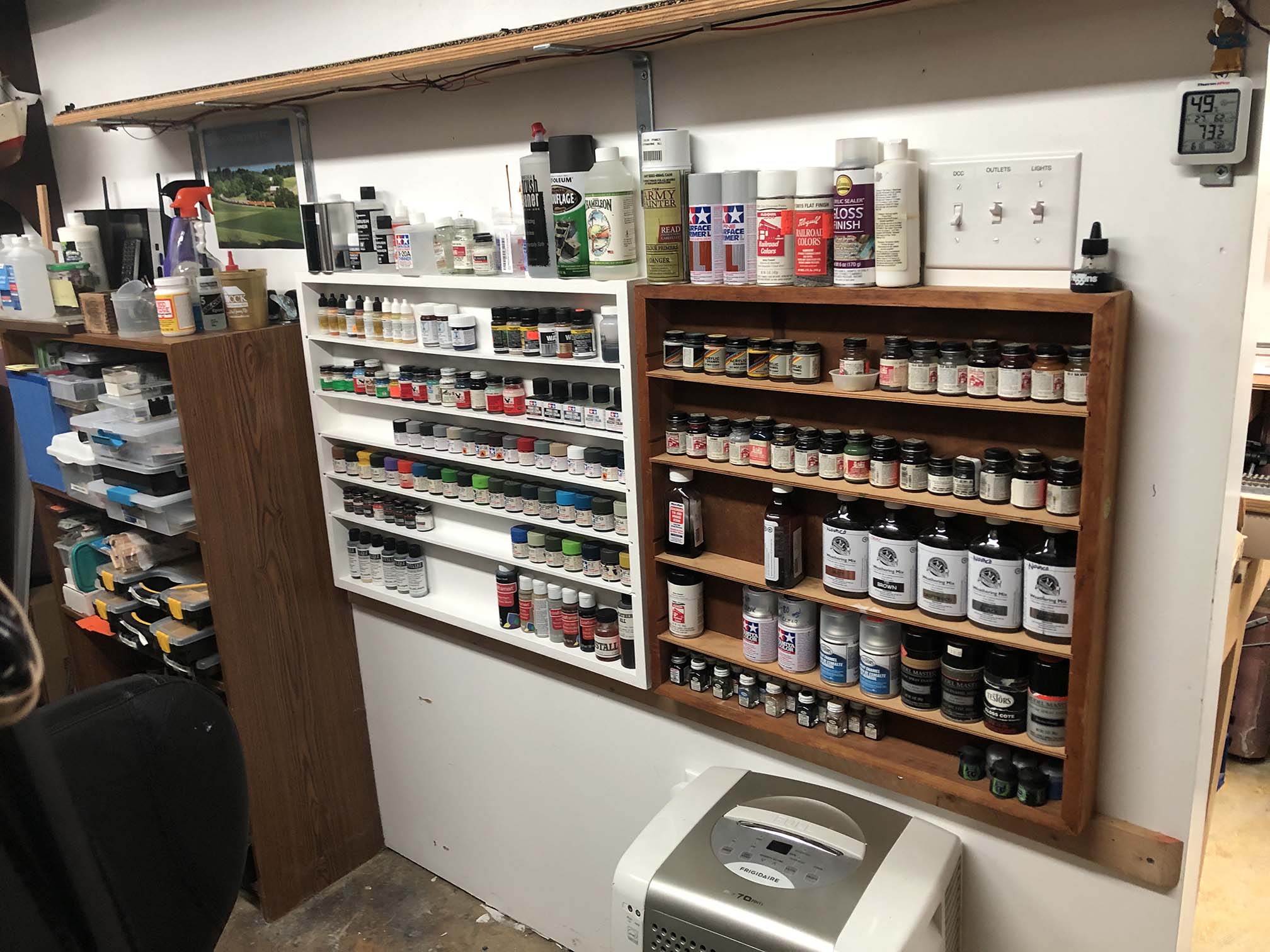
I was gifted some shelving my Grandfather had built for his house on Cape Cod many years ago. It once sat in the laundry room and held baby food jars full of nuts and bolts as well as small jars of oil and other knick-knacks. When the house was being closed up, I had asked for it since I knew it would make a wonderful paint storage rack and currently I was just using a few odd cardboard boxes. Well, over the years I have outgrown that little set of shelves and finally decided to construct some new ones, this time using MDF.
My new shelves on the left, my Grandfather’s shelves to the right.
This project took about a half day, as it took a good bit of ripping and fitting to get everything right. The back and shelves themselves are 1/4″ MDF and the sides are 3/4″ MDF. I used a dado blade set to cut grooves in the sides for shelves and to recess the back panel. In retrospect, I could have recessed it a bit more and could have fit the shelves a bit tighter, but it all worked out just fine in the end. The back was glued and tacked on with nails. Shelves are glued in place. I hand painted it two coats of semi-gloss white, some paint I had leftover in the garage. The fact that the paint is a bit “tacky” means the paint jars don’t slide around on the shelves. The whole thing sits on a rail that’s screwed to the wall, with L-brackets up top screwed into the studs. I modeled it after the shelves my Grandfather built with shelves set to accommodate the various paint bottles I have collected. Overall, I think it’s just right for what I need and it turned out well.
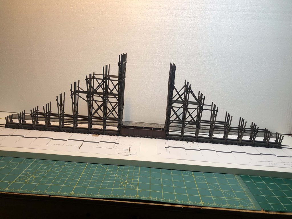
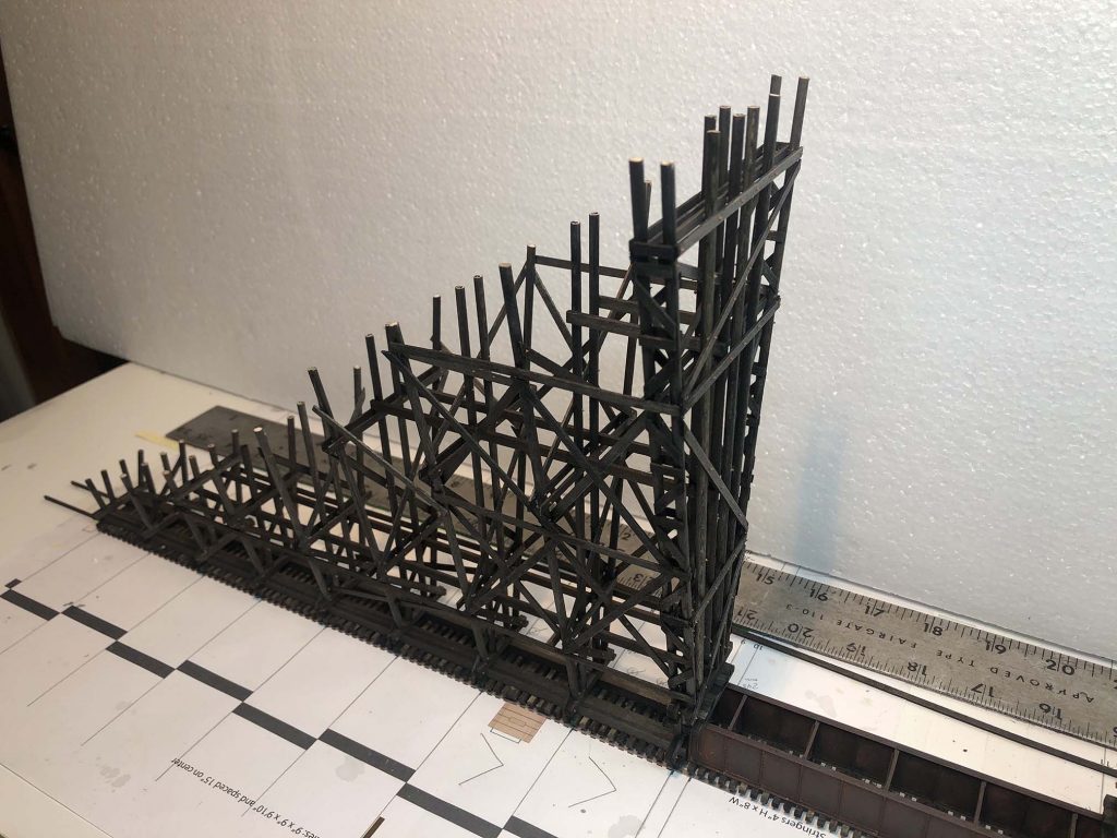
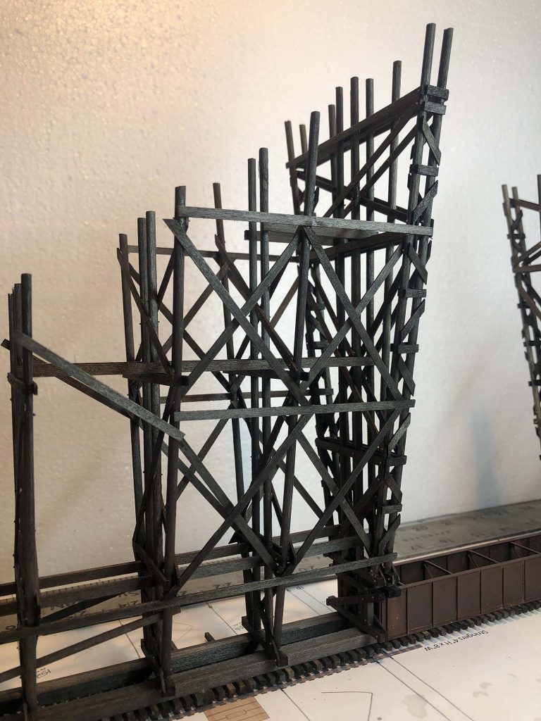
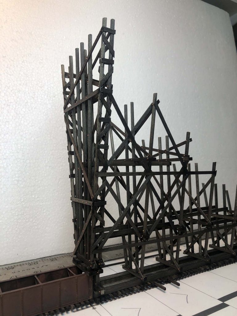
The last several weeks proved to be some of the busiest for me at work and as such progress has slowed. Today, however, I tackled another milestone – completing all of the assembly for the trestle structure itself. I tacked on the final bracing, stringers and girts to complete the lower section. Here’s a few photos of what it’s looking like:
This means that the to-do list is getting shorter and shorter. Here are a few highlights of what’s left:
NBW castings on the side-facing stringers and beams. This will take a good amount of time as I will have to drill and install each one. Much like what I did on the bents, but a bit fewer. I’m not going to install NBW castings on the inner facing beams due to the difficulty in placing them in such tight spaces.
Attach a brace to the bottom of the middle two bents. This will serve as support when the model is turned upright.
Build a sort of cradle to hold the bridge when upright.
Remove bridge from base and flip upright onto cradle/steps.
Build two emergency platforms on the top side.
Install the two beams that run atop the deck parallel to the track, install NBW castings.
Install bracing/walkways that run along top of bents.
Weather and install on layout.
Build and install bracing around lower center bents and cribbing for the ends.
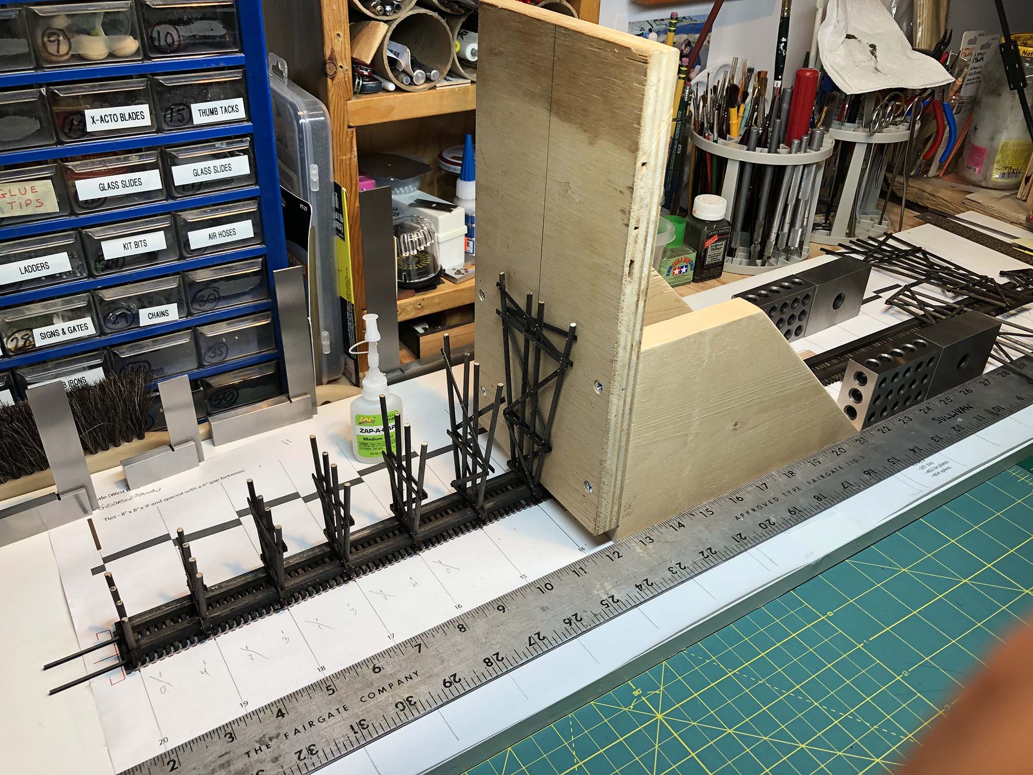
Exactly one month since my last update and I’ve made some great progress on the Rock Creek trestle model that I’d like to share.
All bents are installed and the model is ready for bracing and stringers to be installed.
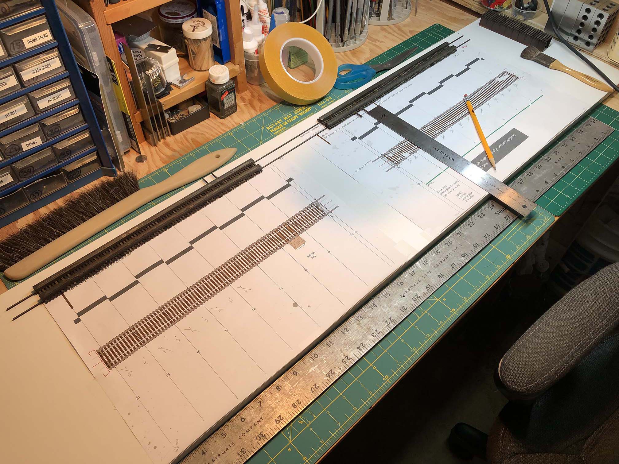
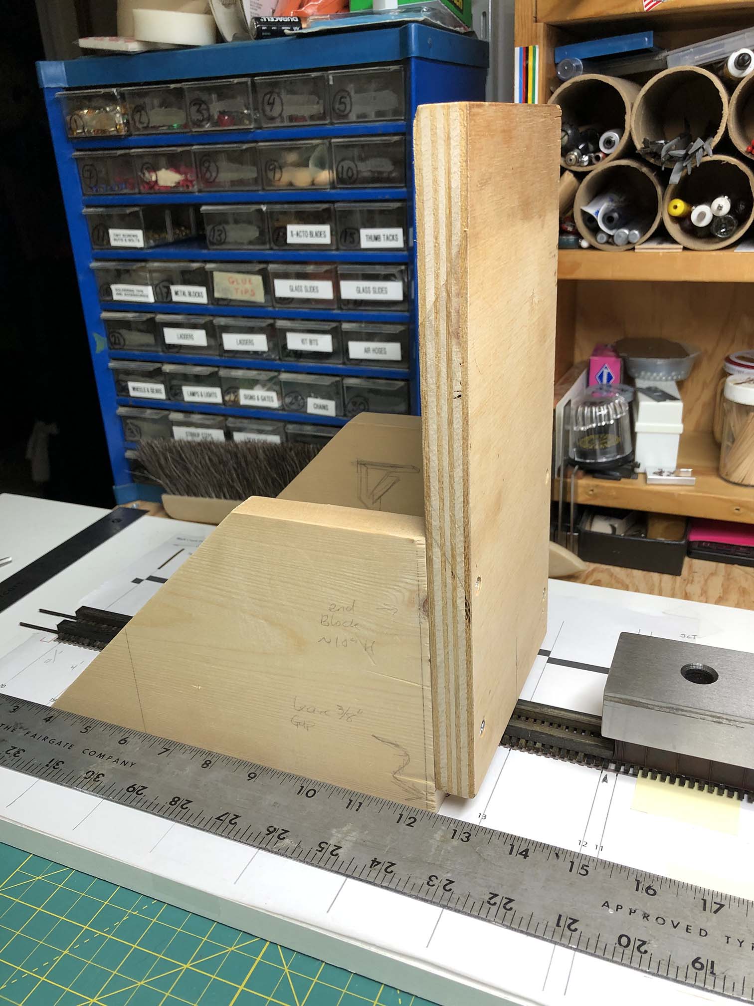
On Friday I built a sled/jig thing to facilitate installing the bents perpendicular and square. More on this in a moment. First up, I needed to flip the top of the bridge over, as it was mounted with track side up. I then took the opportunity to extend the lines that indicated where the bents would be installed, as this would guide my sled/jig later. I also measured where I wanted the straight edge to be and installed it with double-sided tape.
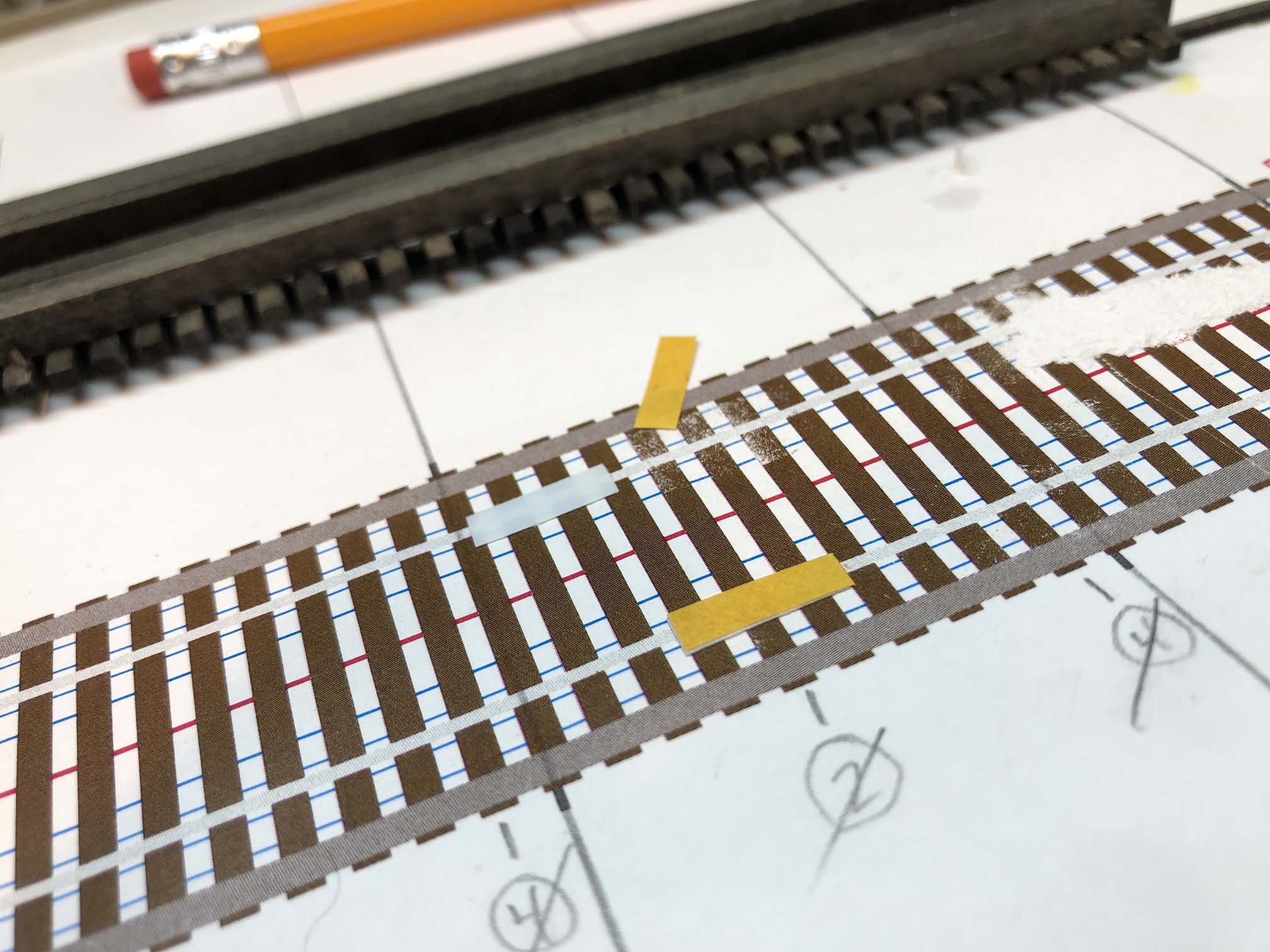
I placed small rectangles of double-sided tape where the rails would lay. Aligned the rails to the plans and pressed gently to set in place over the plans.
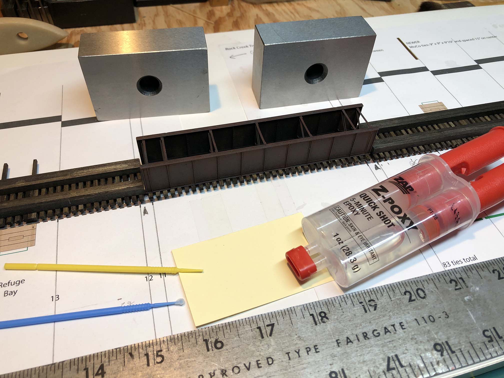
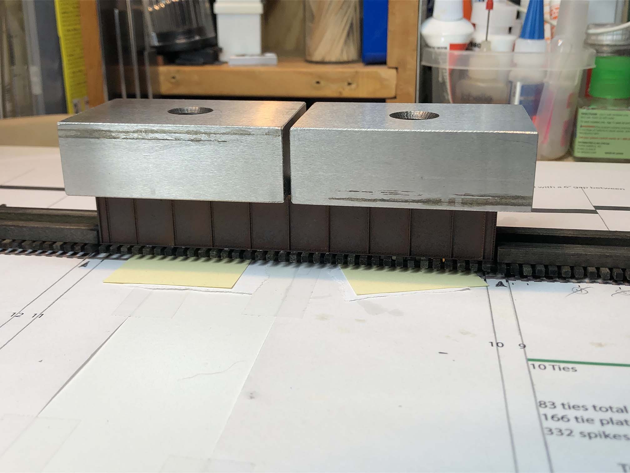
Next it was time to install the center deck girder section (which I had previously built, painted, weathered and installed ties and tie plates). I prepared some 5-min epoxy and lightly brushed it to the back side of the rails. I carefully positioned the bridge in place and weighed it down while the glue dried.
Getting ready to fasten deck girder to rails with epoxy.Weights holding deck girder center section down on the rails while glue dries.
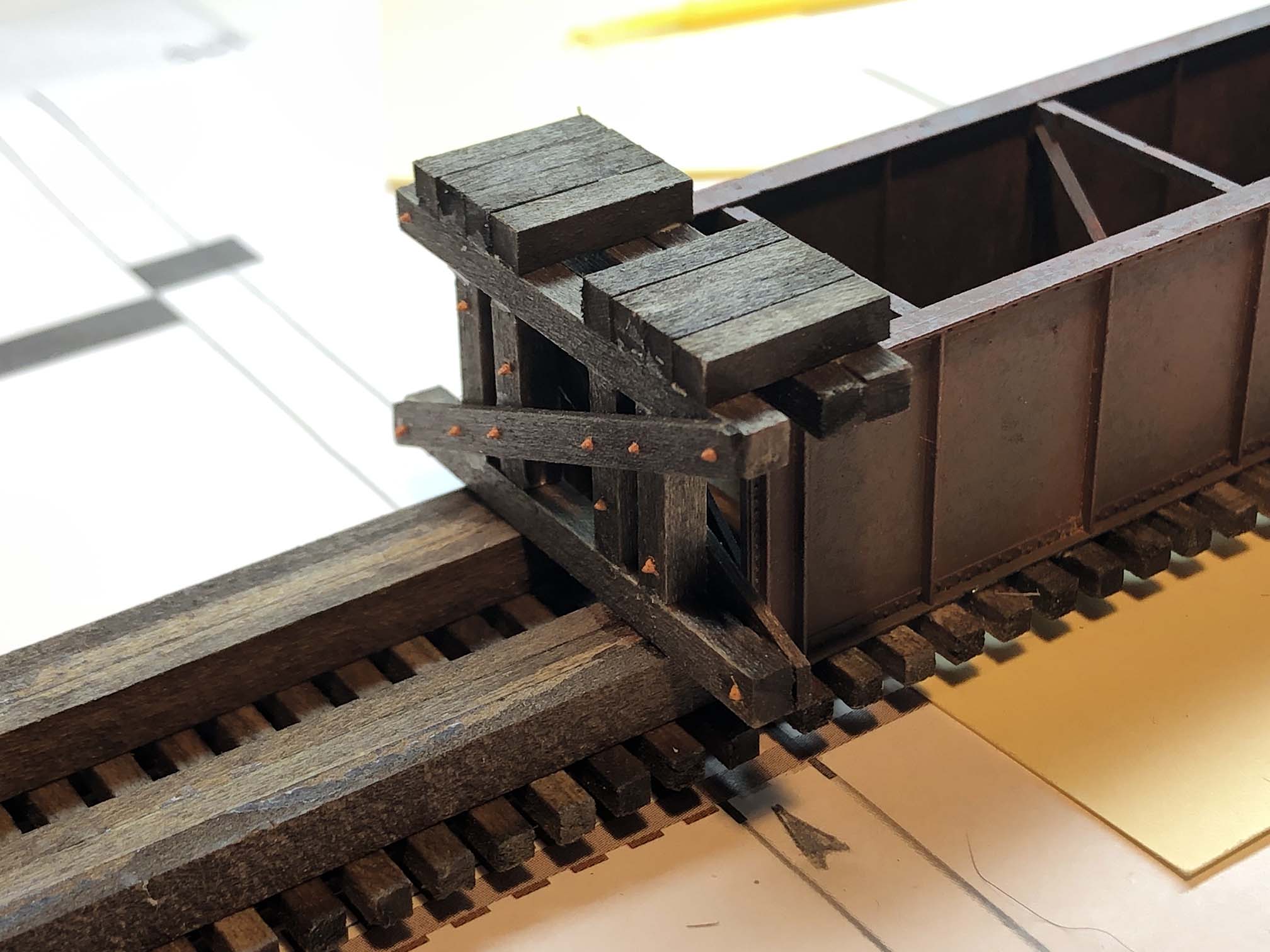
I then completed the blocking around the deck girder.
Close up of the blocking around the deck girder bridge section.
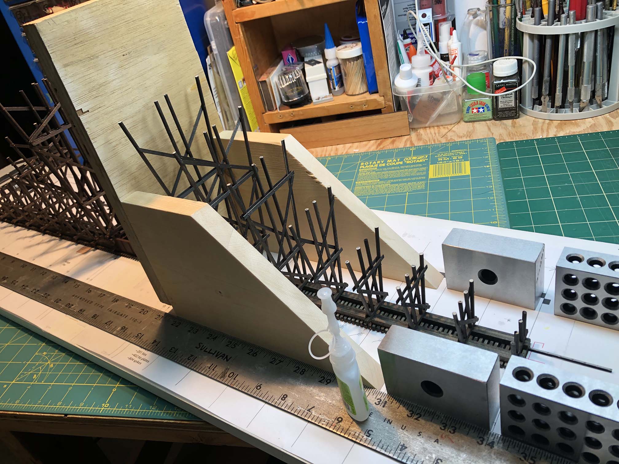
The sled/jig allowed for me to install the bents perpendicular and square to the base. This took a bit of finagling to get set up properly but made the job go fast once the system was in place.
Sled for aligning bents. Rides along straight edge. Overall view of sled and plans. Sled in action, installing bents.
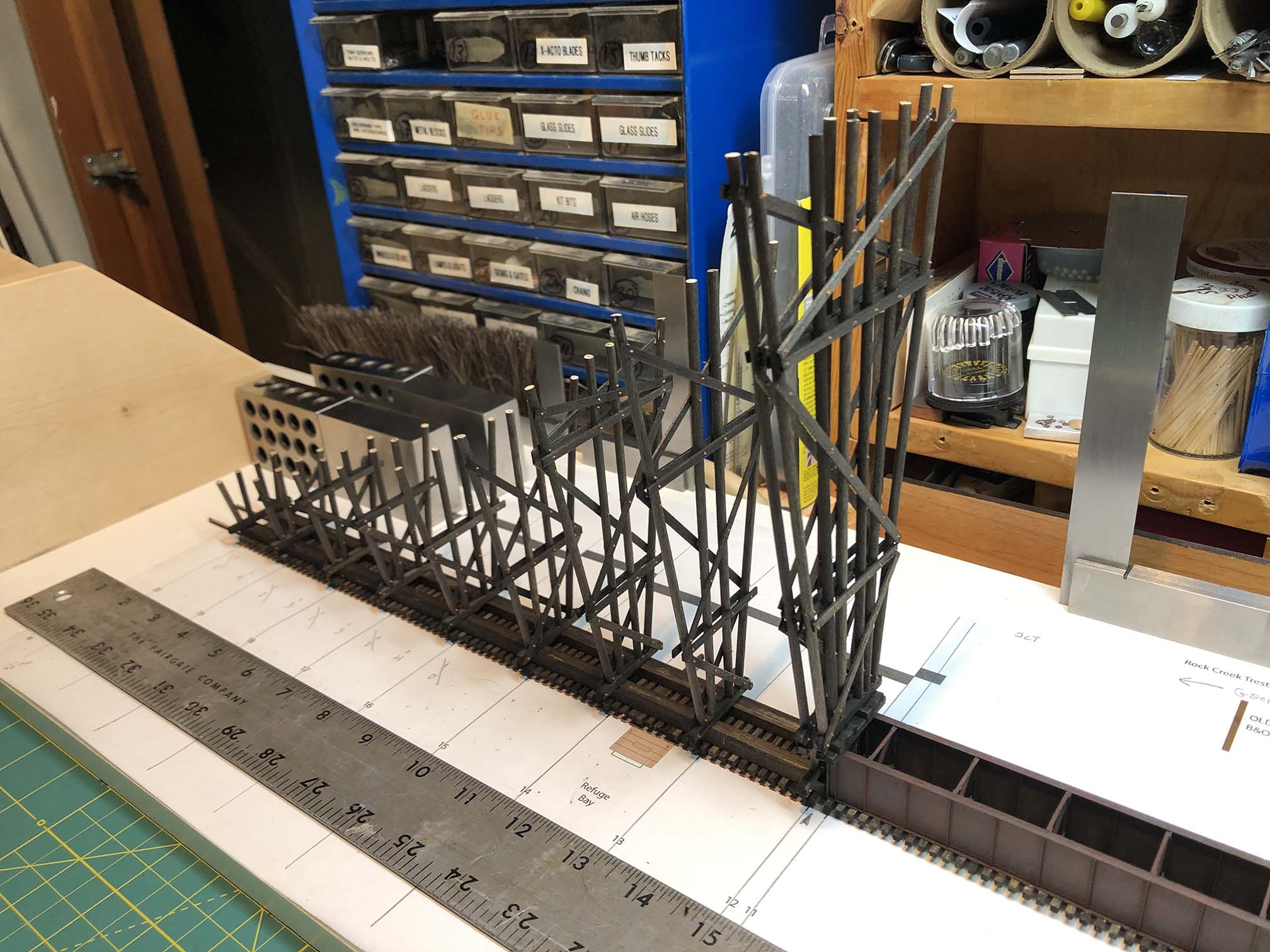
Halfway there!
Nearly done with the East end. When I reached the center, I flipped the sled around and faced the center section to install the two bents at the end.
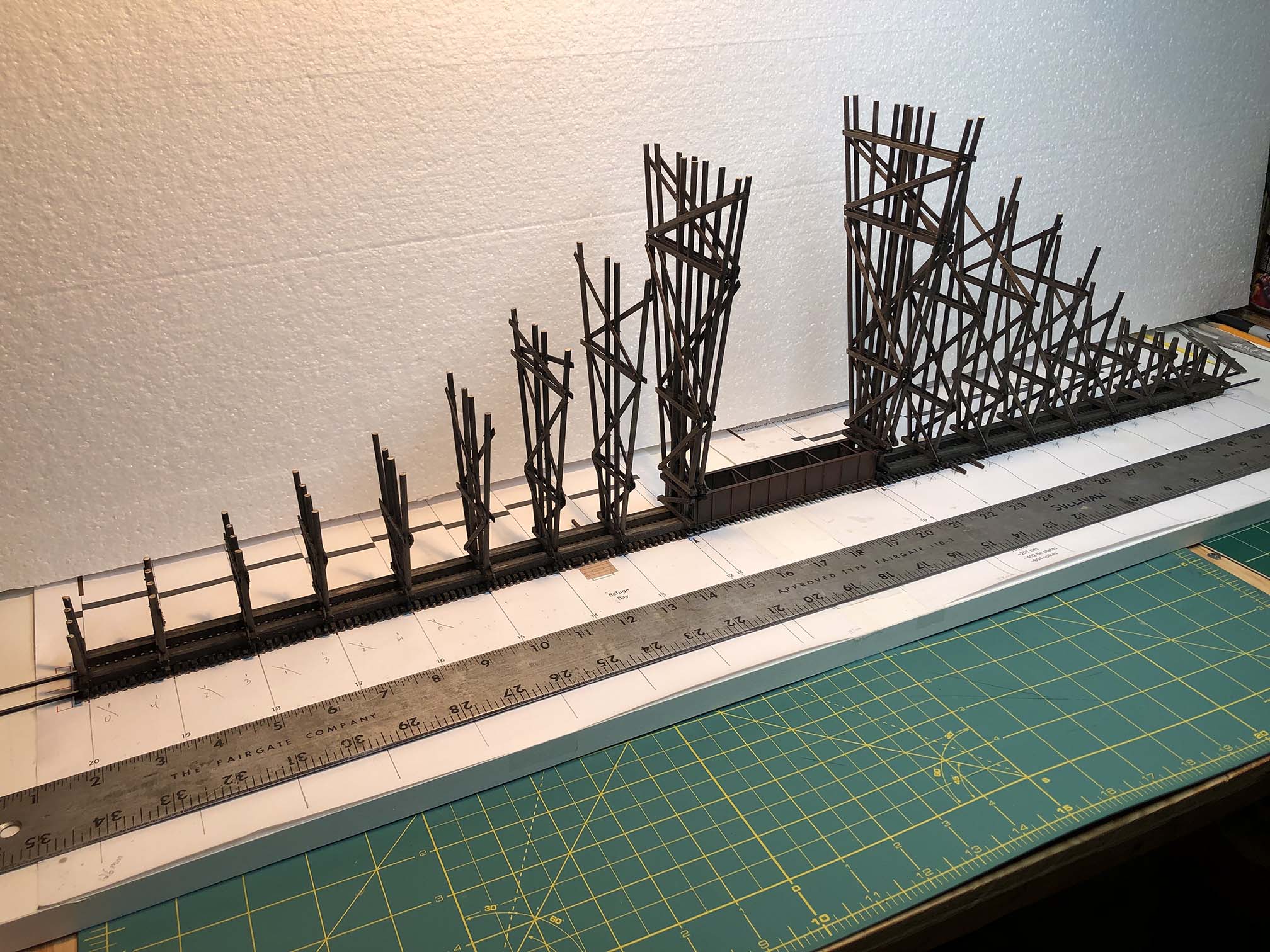
And here we are with the completed bents. It’s looking pretty good!
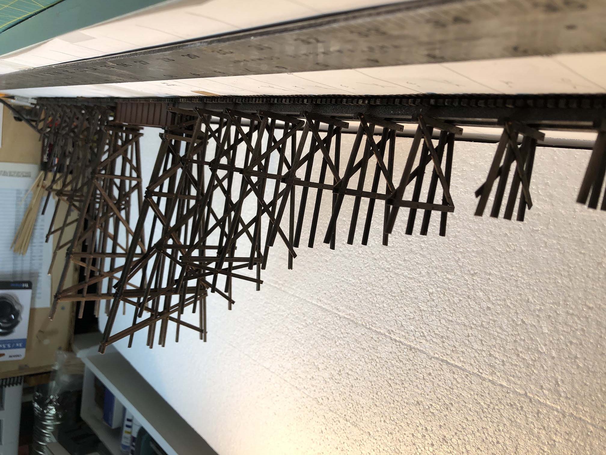
If you flip over the photo you can sort of get a feel for what the completed model will look like.
Ok – that’s all for now. I’m very pleased with how this is coming along and up next I’ll be installing all of the stringers and girts to get this over the finish line! Stay tuned…
April 2, 1956. Heading west down the Branch from the Junction. On the right is the long E.C. Keys warehouse atop the retaining wall. To the left of the train is the coal trestle lead track. The old B&O MOW X-358? M-15 boxcar is sitting on a storage track. Photo by R. Mumford. B&ORRHS Collection.
(NOTE: UPDATED DRAWING TO v2 BELOW 7/3/2022) Just about a hundred yards west of Georgetown Junction was the Enos C. Keys & Sons company that sold building materials, aggregates, merchandise, coal and fuel oil from 1889 until 1978 when it finally went out of business. On the North side of the Georgetown Branch track, a turnout branched off and climbed up a steep embankment and sat atop a high retaining wall where it served a warehouse for building materials. Aggregates would be unloaded over the side of the retaining wall via chutes, down into large sorting bins below. On the south side of the GB tracks, a turnout diverged, rose slightly, and then out on a coal trestle that was approximately 227′ long (based on aerial images). This trestle also served as an unloading platform for fuel oil. In the very far northwest corner of the property, at the intersection of Brookville Rd & Stewart Av was the scale house, which was torn down recently. In a strange twist of fate, a fellow GB-served industry, T.W. Perry, is now occupying the E.C. Keys space atop the retaining wall. The lower area where the coal dock was is now a long warehouse building. Much of this will likely (or already has) change once the Purple Line construction is completed.
Feb 22, 1958. Heading to Georgetown. Another view of the trestle lead and warehouse/retaining wall. This is the BEST photo I have of the coal trestle… and it’s not even in the photo! yep! Photo by R. Mumford. B&ORRHS Collection.
For my model railroad, I am modeling the coal trestle, retaining wall and siding, and the long lumber warehouse.
This view of the layout should give you an idea of where things will go. The coal trestle is going where the small trestle is in this photo, the retaining wall will be along the high siding.
I decided to spend some time studying the site and develop a plan for my model of the trestle.
A snip of the 1957 aerial view from Historic Aerials. Note the fuel storage tanks to the southeast. The scale house was up in the upper left hand corner. Also note the boxcar sitting on the end of the retaining wall siding next to the lumber shed.
Using the scale tools available on the Historic Aerials site I was able to get basic measurements of the trestle. Approximately 227′ long, 15′ wide, bents (bins) about 15′ apart. This was enough to get me going, along with other details in the coal yard that I could observe. I now needed to figure out what sort of prototype to go after. Of course, without a photo I have no idea what the design of this trestle was derived from, but a good starting place was with the B&O Standard Plans book. I happened to have one that covers such things:
B&O Railroad, Roadway and Track Standards, 1945 (rev 1948); Commercial Coal Dump, Timber Construction. Book available from B&ORRHS, item 72047.
This fantastic reference book is available through the B&ORRHS Company Store, now in digital format. I highly recommend it! After some mocking up on my model railroad I realized that I wouldn’t be able to model a whole 227′ trestle and needed to reduce the size. I settled on a nice 135′ which will allow three 40′ cars, two less than the prototype would have held. This would work nicely for my small layout and even at this small size would still be a formidable structure. (I sure am building a lot of trestles on this layout… sheesh. I’ve got about four more to go, but that’s for another day!)
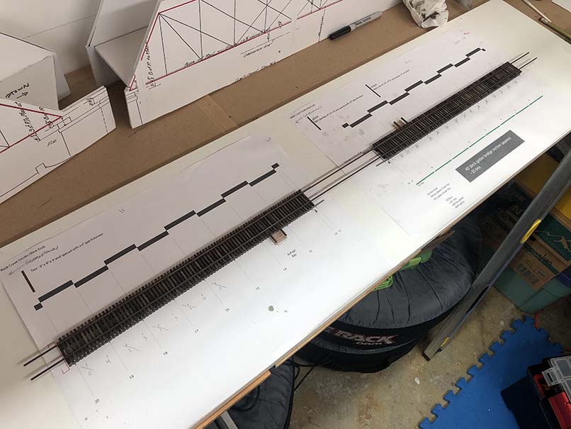
So, using Adobe Illustrator, the B&O plans and some photos I found online of similar structures & models, here is what I came up with:
So the image is quite wide – click for a larger view. I hope this gives you an idea of the design I’m after. I tried to stick as close as possible to the B&O design, but added a few modifications that I felt were necessary. One was the inclusion of additional supports for the walkway, a wider walkway, along with a railing. I also made some slight height adjustments but stayed within the requirements laid out in the B&O plan. All in all, I think it’s a good representation of the trestle and will make a very nice model. If you’d like a copy of the vector file, it’s below as a PDF for your own personal use. (NOTE: UPDATED to V2 7/3/2022)
The E.C. Keys facility will be a key scene on my layout. It’s a fascinating area to switch and this coal trestle will be a centerpiece of the small industrial area. Now to finish the Rock Creek trestle so I can get on with building this!
I know, I know, the trestle has been moving forward at the speed of slow. It’s been a while since I made an update so I figured I’d put a stake in the ground and share where I’m at.
20 bents, completed and arranged in order
Last Tuesday during my train club “Bench Time” I finished the last of the 20 trestle bents. Yesterday evening I touched up any of the unstained ends of wood that I missed and installed a few NBW castings that I missed. They are done! I consider this a big milestone. On to the next step.
The trestle deck
I spent some time cleaning up the trestle deck and clearing space for assembly. My plan here is to build a sort of sled with a flat vertical face to lay the trestle bents against for installation. I will keep it square by mounting a straight edge along one side that the sled can slide against. More on this in a future post.
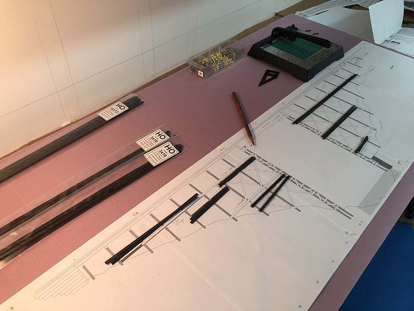
Cutting stringers and girts
Finally, I laid the side view schematic out on some 2″ foam core and began to cut the various stringers, girts and braces that will go on the trestle sides. I need to cut, sort, prep and arrange all of these pieces before I can begin to install the trestle bents to the top deck. I have this weekend off so I think I will try to make more progress.
The project is coming along nicely. The last several months have been busy and as such this fun project has been going slowly. I have mainly assembled trestle bents during train club Zoom meetings. One or two a night, every week or so. I’ve also been working on a few other projects. I’m good at starting projects; bad at finishing them. Can you tell?
It’s a rainy, wet, dreary day here in Maryland; AKA perfect model railroad weather. Decided to put a kit together today so I’m digging into this old Branchline 50′ B&O M-61 boxcar kit.