Recently Lance Mindheim visited Kelly Regan’s Georgetown Branch layout and did a very nice writeup on the project! I highly recommend you visit Lance’s blog and have a look. Bravo, Kelly!
Category Archives: Model RR
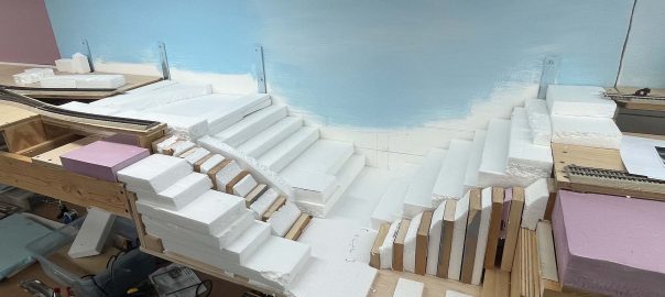
Layout Progress – Lower Deck
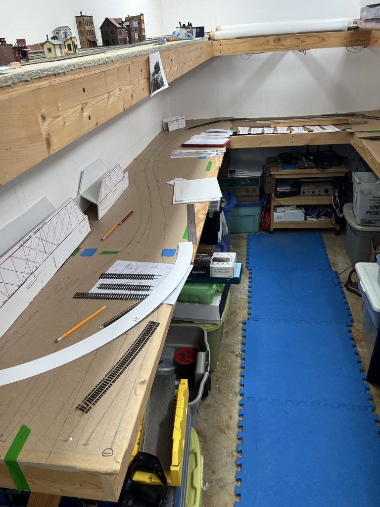
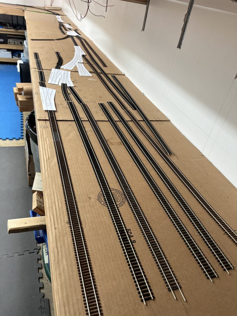
Over the last two weekends I managed to squeeze two big work sessions in and made some great progress. First up was nailing down the rough track plan based on lots of trial and error over the last year.
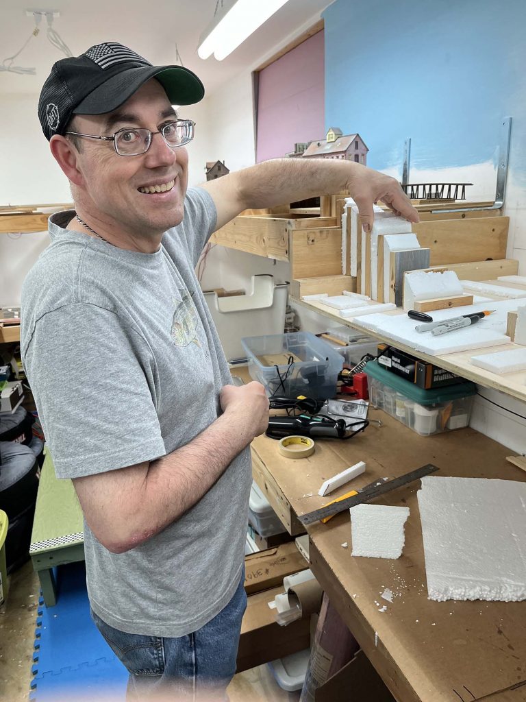
So, this weekend Kelly was able to swing by and we had a marathon construction session. After checking all of the templates and doing a lot of measuring, we took them up to the garage for some cutting.
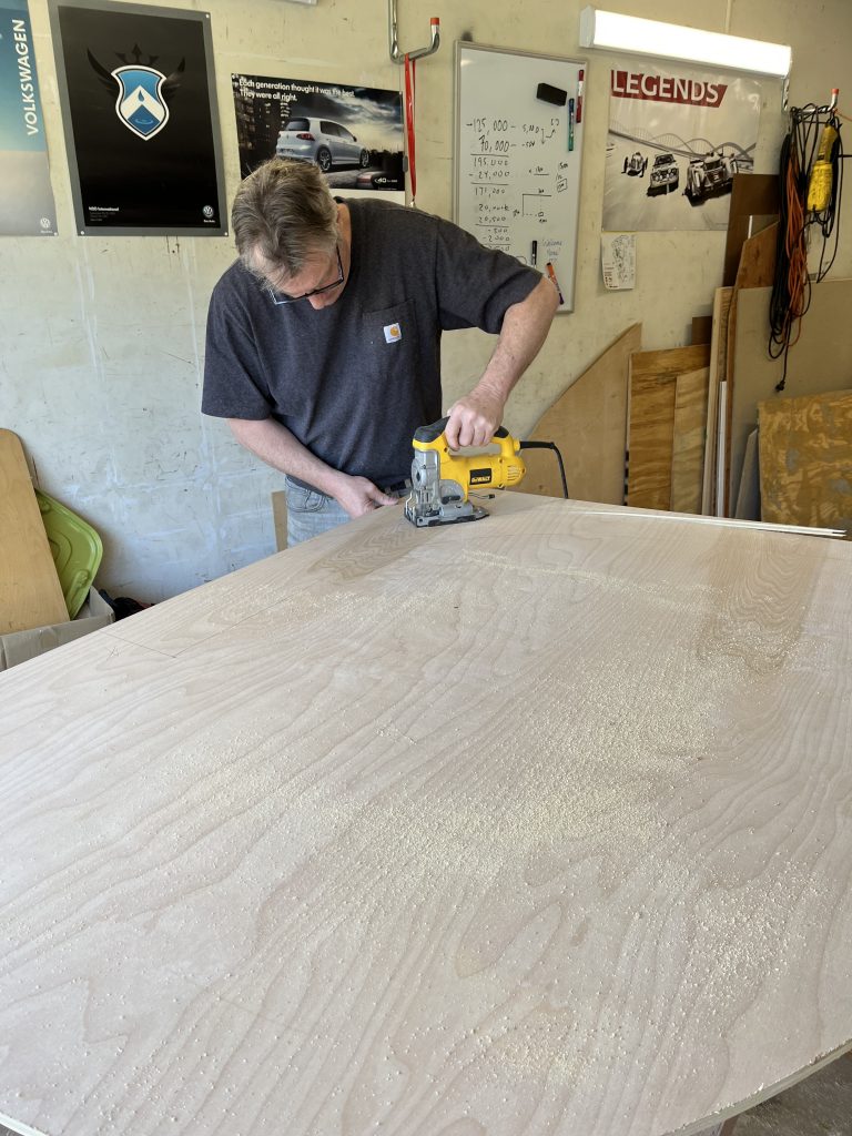
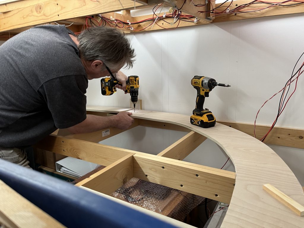
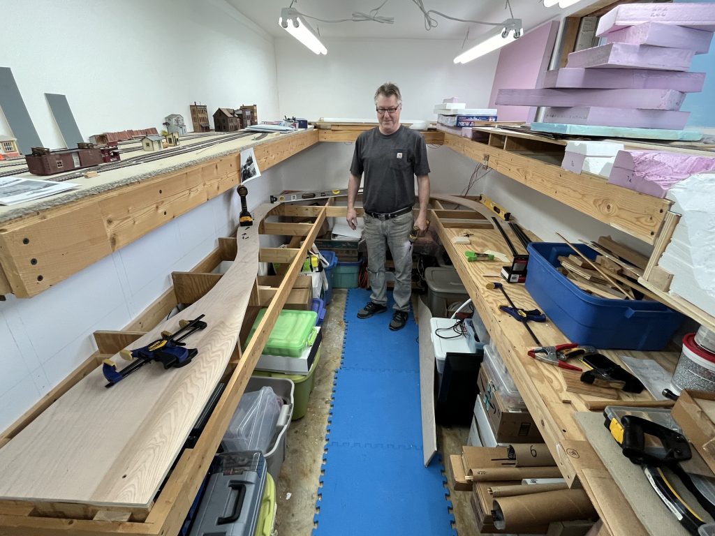
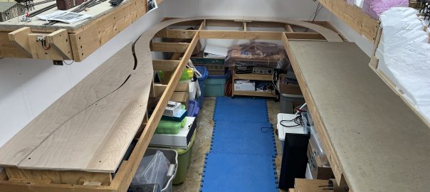
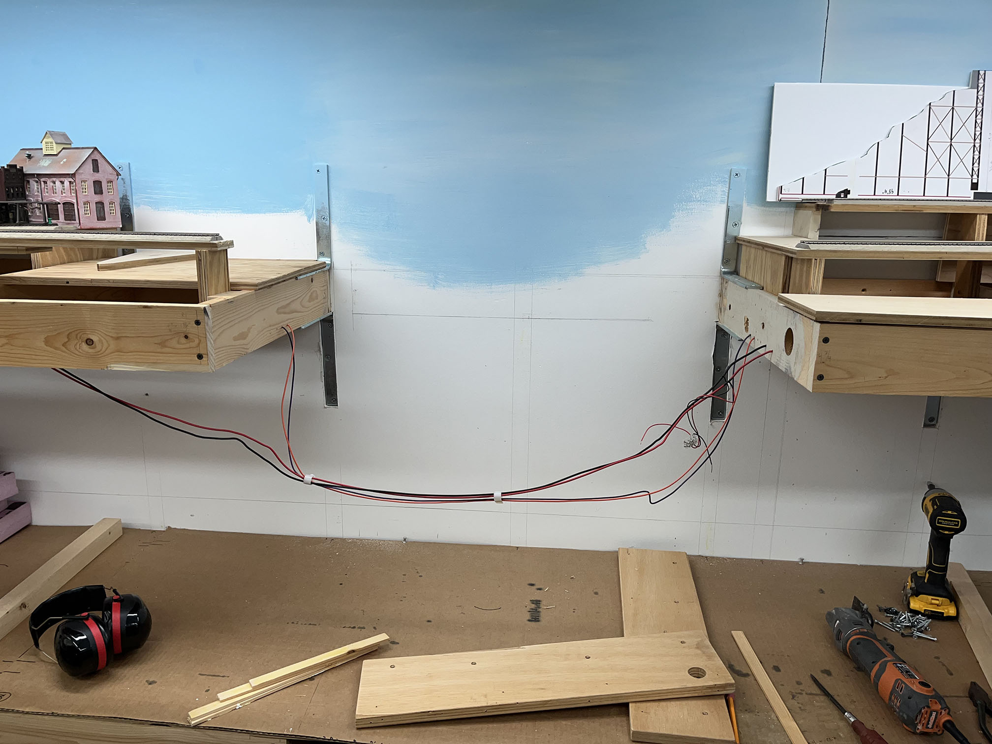
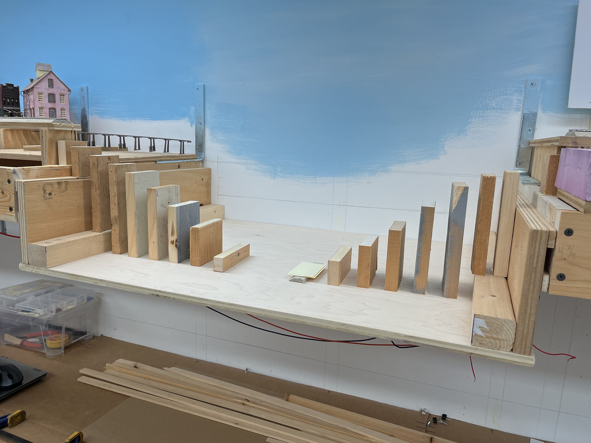
After cutting the sub roadbed and splicing it together, we measured and cut risers. We then spent a considerable amount of time figuring out the grades, as Dalecarlia is a few inches higher than Georgetown on the layout. After a LOT of fiddling and experimenting, we got it figured out and permanently installed the risers. Last was cutting and installing Homasote over all of the Georgetown waterfront area (the plywood-covered sections.) It turns out I was shot one 28″ square piece, but thankfully Kelly has some extra at his house that he is going to give to me. Sweet! Here are a couple wrap up photos of what the layout currently looks like:
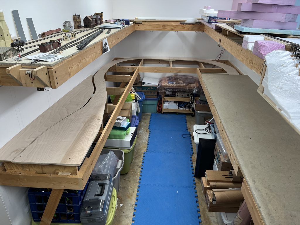
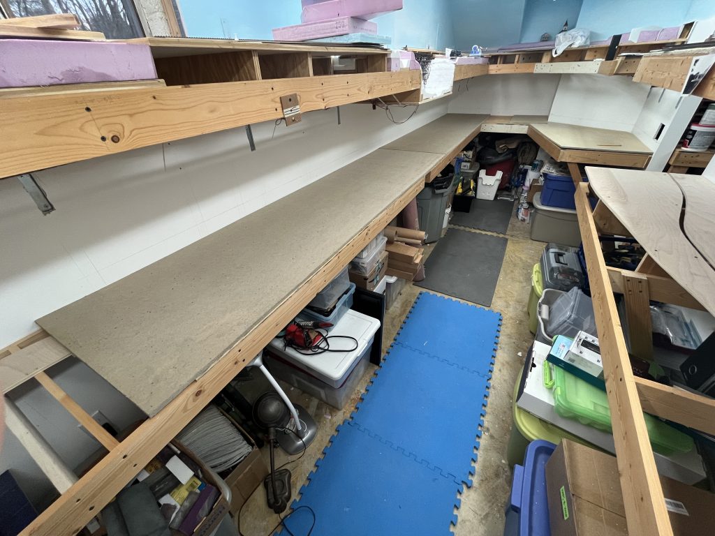
Next steps are to do a bit of finishing on the Homasote and fasten it to the plywood base. I will also finish designing and building the bridge from the helix into the layout room, which will be a basic sheet of plywood and Masonite. I then need to empty out the room so I can get under the layout to cut holes and run bus cables. I need to do some work on the walls and figure out the backdrop corners as well as a few other things. A huge thanks to Kelly for pushing me today to get all of this done! The most progress I’ve made in a very long time.
Onward.
Rock Creek Trestle Test Run
Sometimes you just gotta run some trains…
Just a quick test run. 🙂
Freight Cars in Georgetown, March 1949
The National Archives has a magnificent set of photos from the construction of the Whitehurst Freeway. Naturally, there are some wonderful trains caught in the shots and I’d like to document them here.
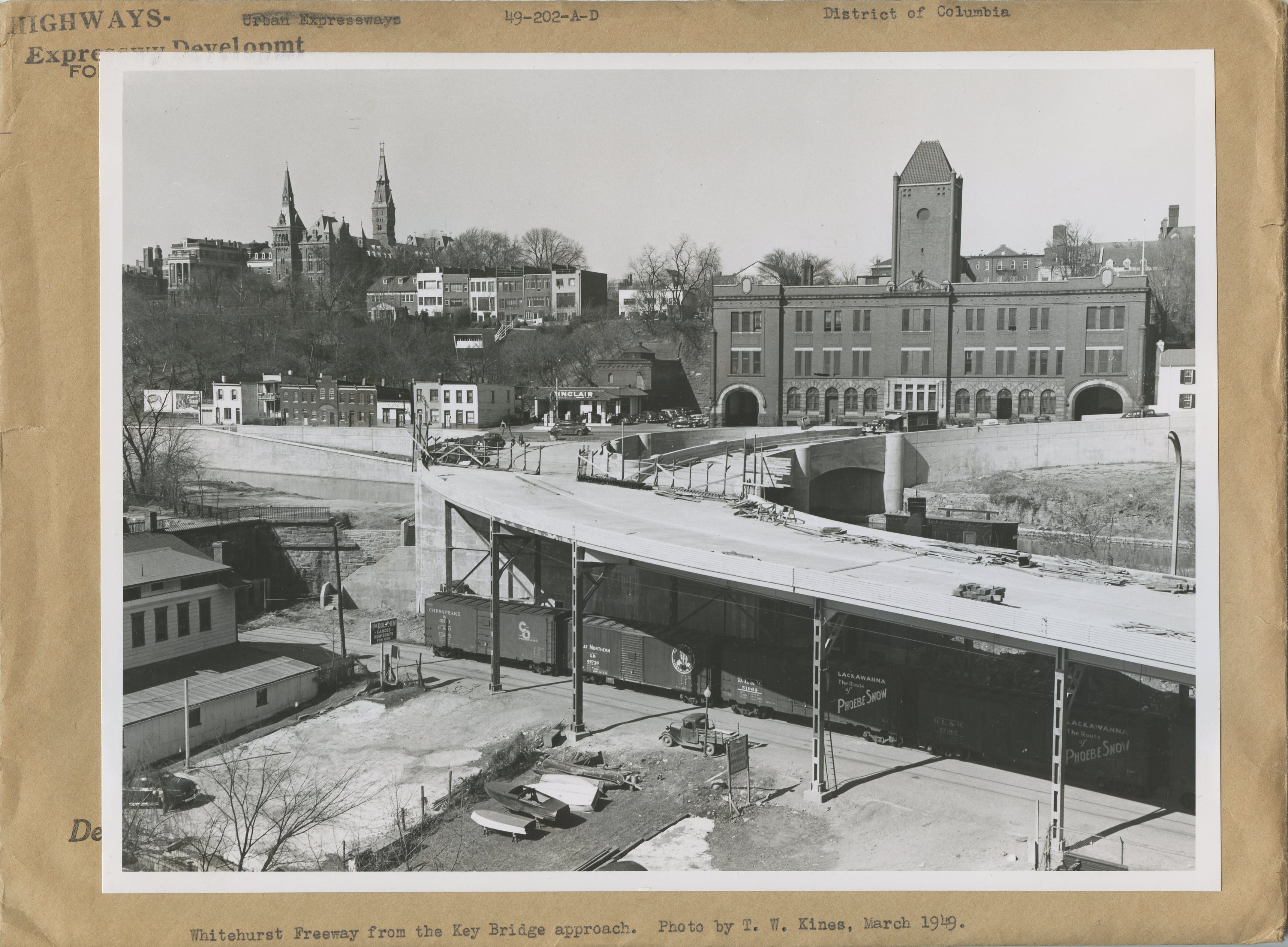
First up is this shot from March, 1949. There are actually a couple prints from this day, showing these and some other freight cars. I imagine the Georgetown switcher was hard at work preparing the train for the Georgetown Turn or perhaps receiving some new cars into the yard. Regardless, it’s a pretty special photo. Before we go on, a huge shout out to the Steam Era Freight Cars group for car data and other info, as well as the various manufacturer pages linked below. Let’s dive in.
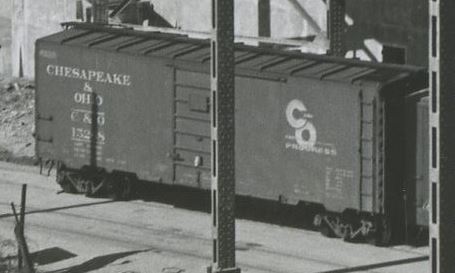
Chesapeake & Ohio 152×8
This is a Pullman-Standard Co. built 40′ PS-1 boxcar, lot 5886, C&O series 15000-15999 (1,000 cars), built in Feb 1948. It has 6′, 7-panel Superior doors (evenly spaced, placard mounted to stiffener), Ajax hand brake, Apex Tri-Lok running boards, A3 trucks, 12-panel sides.
Kadee produced a similar model of this car in HO scale, #5023.
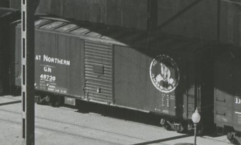
Great Northern 49730
In 1940-41 GN received 3,000 cars of this type, built by Pullman Standard, American Car & Foundry and others. This car was built by Pullman-Standard Co. in 1941 in a lot of 500 cars. This 40’6″ car features a 6′ Youngstown door, steel frame, steel ends, wood sheathing. Note that this car has a rare front-facing goat logo, with the slogan: “SEE AMERICA FIRST, GLACIER NATIONAL PARK.” GN specified boxcar red sides with a black roof, ends and underframe.
Resin Car Works produced a similar model of this car in HO scale, Kit 11.01.
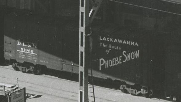
Delaware Lackawanna & Western 51963
This car is an AAR 1937 design boxcar from DL&W series 51750-51999, built Dec 1944 by Magor Car Co. lot W708, a total of 250 cars. The car features 10′ IH, 6′ seven-panel Superior doors, 10-panel riveted sides, 4/5 Dreadnaught ends with round corners and no push-pole sockets. Murphy raised-panel roof, Ajax handbrake, wood running boards, T-Z brake step, 7/7 ladders, double-truss, spring plankless trucks with cast iron wheels. These cars were built between Dec 1944 and Feb 1945.
Rapido Trains has just announced a run of AAR 1937 cars and feature this paint scheme in a slightly different series. SKU 181002A. Atlas offers an entry-level version of the AAR 1937 boxcar as well. From what I can tell, the Intermountain 1937 AAR boxcar has square corners only and is not ideal. They do offer a DL&W paint scheme on the square corner car.
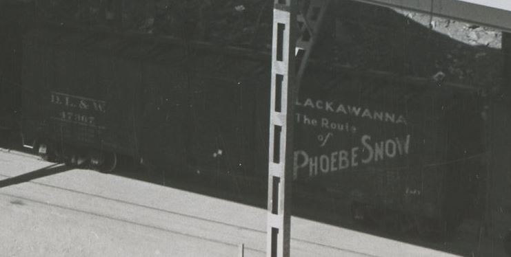
Delaware Lackawanna & Western 47367
Between Nov 1929 and Feb 1930 DL&W took delivery of 1,000 of these unusual cars were derived from the USRA standard design. These all-steel boxcars were from series 47000-47699, 700 cars, built by American Car & Foundry, Lot 998, delivered Nov 1929 – Jan 1930. (The other 300 cars, 47700-47999, were produced by Magor Car Co. Lot P-7072, delivered Jan-Feb 1930.) Cars had an insight height of 8’7″, Hutchins Dry Lading roofs and Youngstown doors. After 1940 when cars were outshopped and AB brakes added, many were outfitted with Murphy panel roofs, steel running boards and Superior panel five-panel doors. Cars were delivered in DL&W freight car brown, with standard white freight lettering. Repaints began in 1942 and included the addition of the “Phoebe Snow” slogan design. In 1955 many of these cars were repainted a second time and received the large” “Billboard” road name stenciled and moved to the left side. (Special thanks to Brian Carlson from the Steam Era Freight Car group and Protocraft for some of this info!)
Ozark Miniatures produces a decal set for these cars in HO scale. Tichy also offers three decal sets for variants of this car. (one, two, three.) As does K4. Decals for O scale cars produced by Protocraft. Apparently the Broadway Limited NYC 40′ Steel Boxcar is a close match to the DL&W prototype, but lacks the correct ends. It can be kitbashed into a stand-in.
I hope you’ve enjoyed this dive into some freight car specifics. I know that I’ll be hunting some models of these cars for my roster!
August 2023: Progress Update: Rock Creek Trestle & More
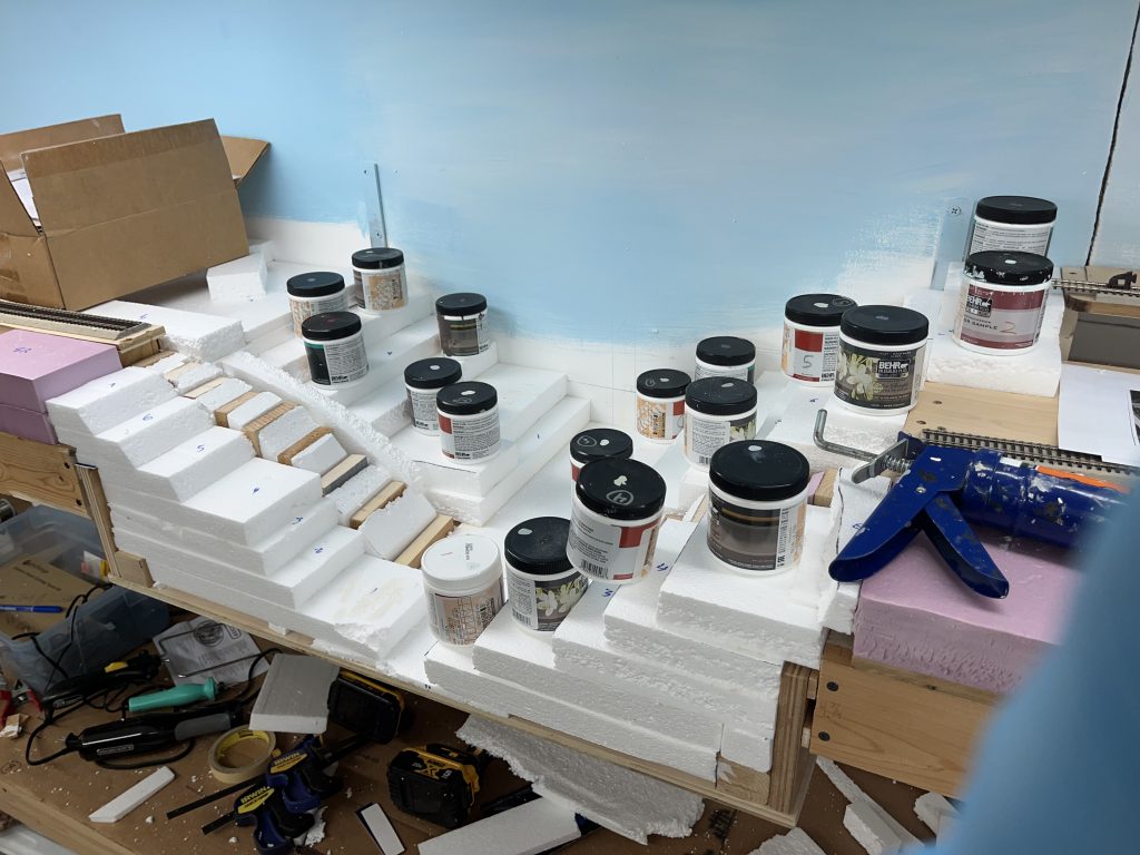
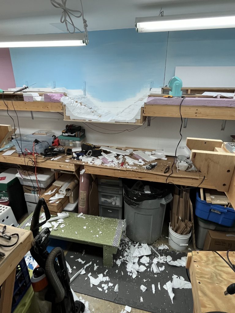
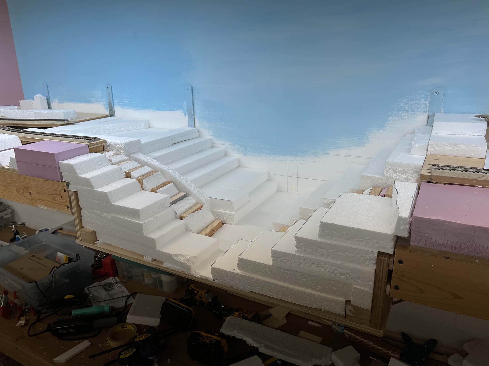
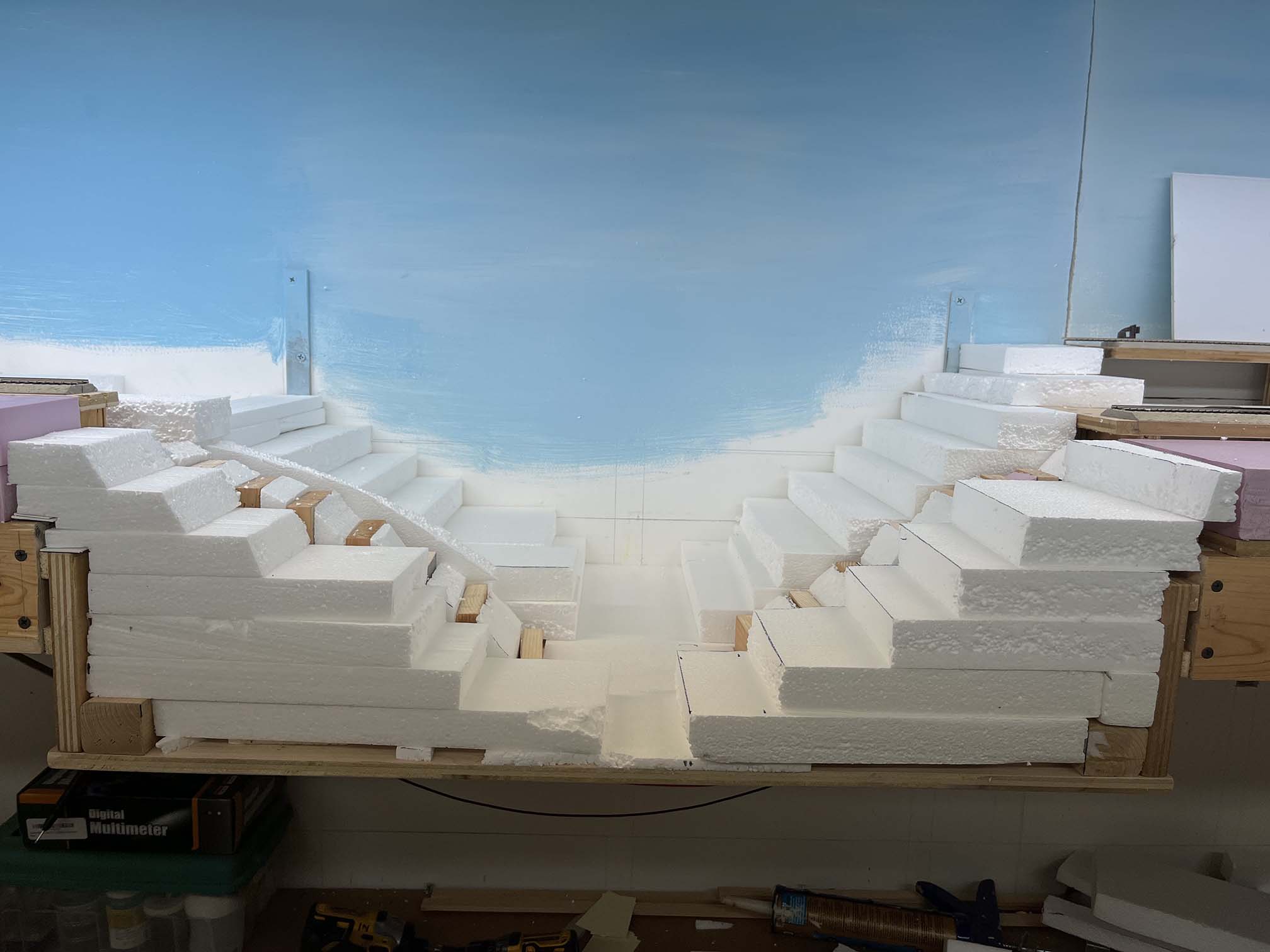
So are you sick of me posting “updates” on the Rock Creek trestle yet? Yeah, me too! 🙂 Anyway, onward. Made a bit of progress on the Rock Creek trestle scene. First up, some terraforming. That requires gluing all the foam I cut in an earlier work session. After some research, I settled on this stuff:
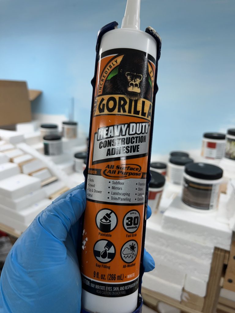
Worked a treat for gluing all the foam together.
Next up came the actual carving with foam cutting tools, knives and a rasp. I wore a respirator mask, had a fan on, and a powerful extraction fan running while working with the foam cutting tools. The fumes are nasty!
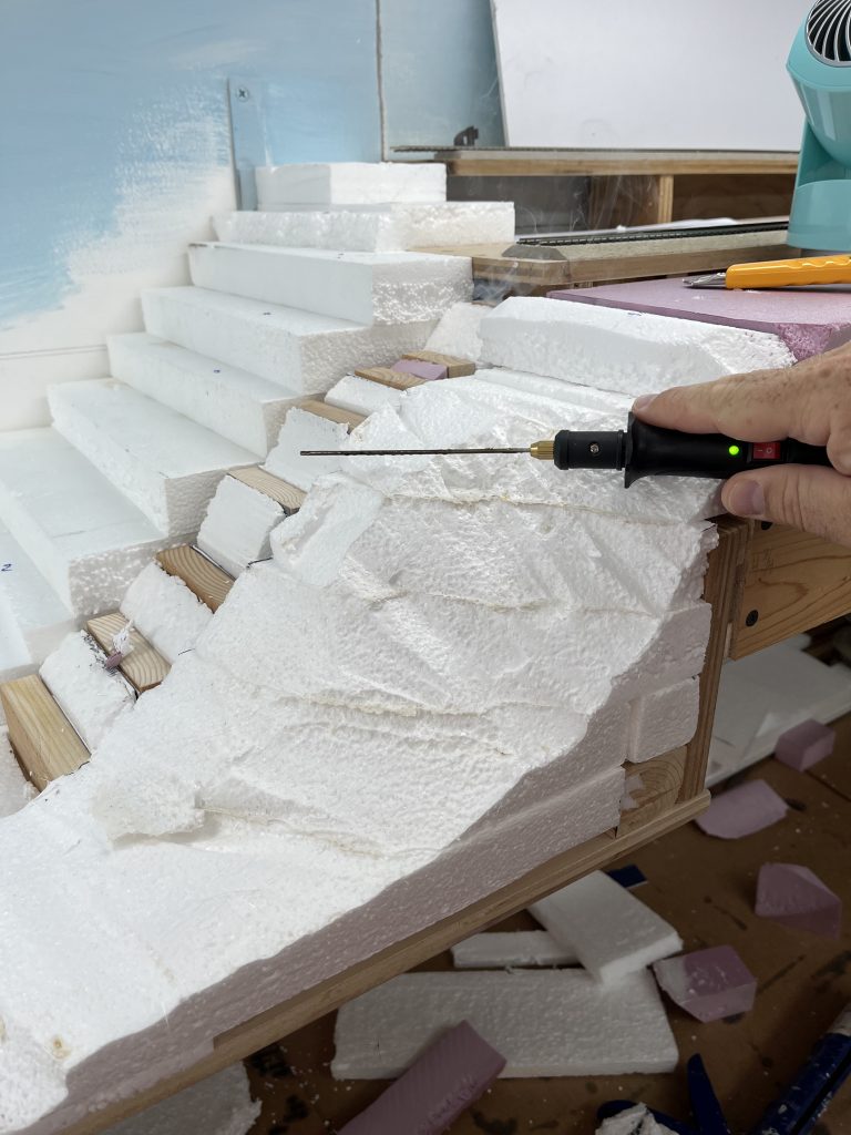
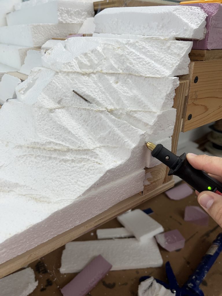
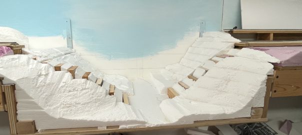
After all was done, things are starting to come together
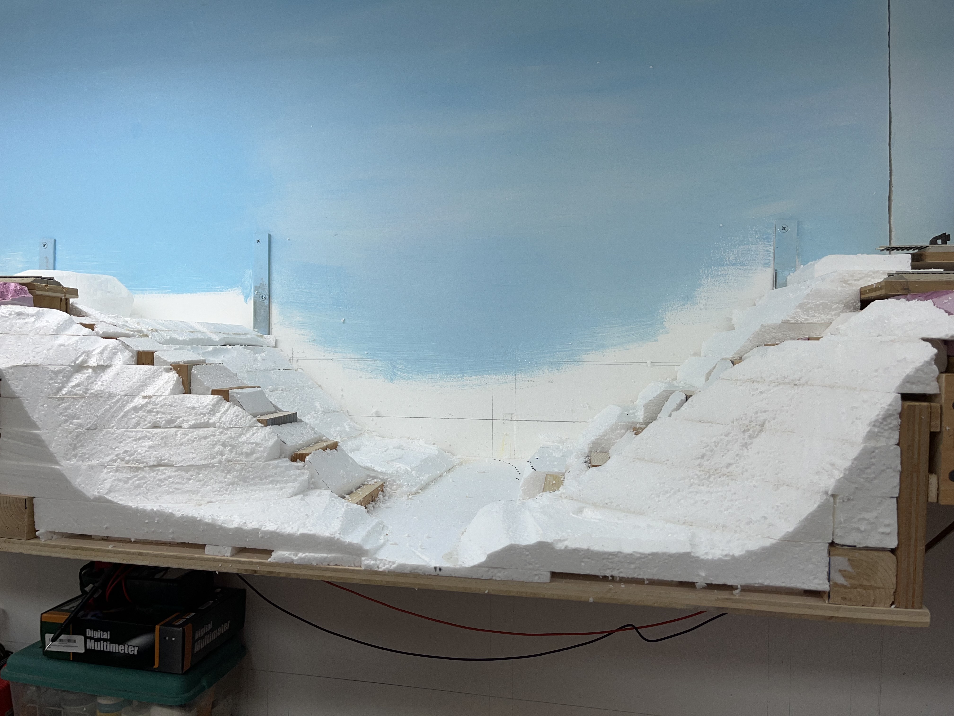
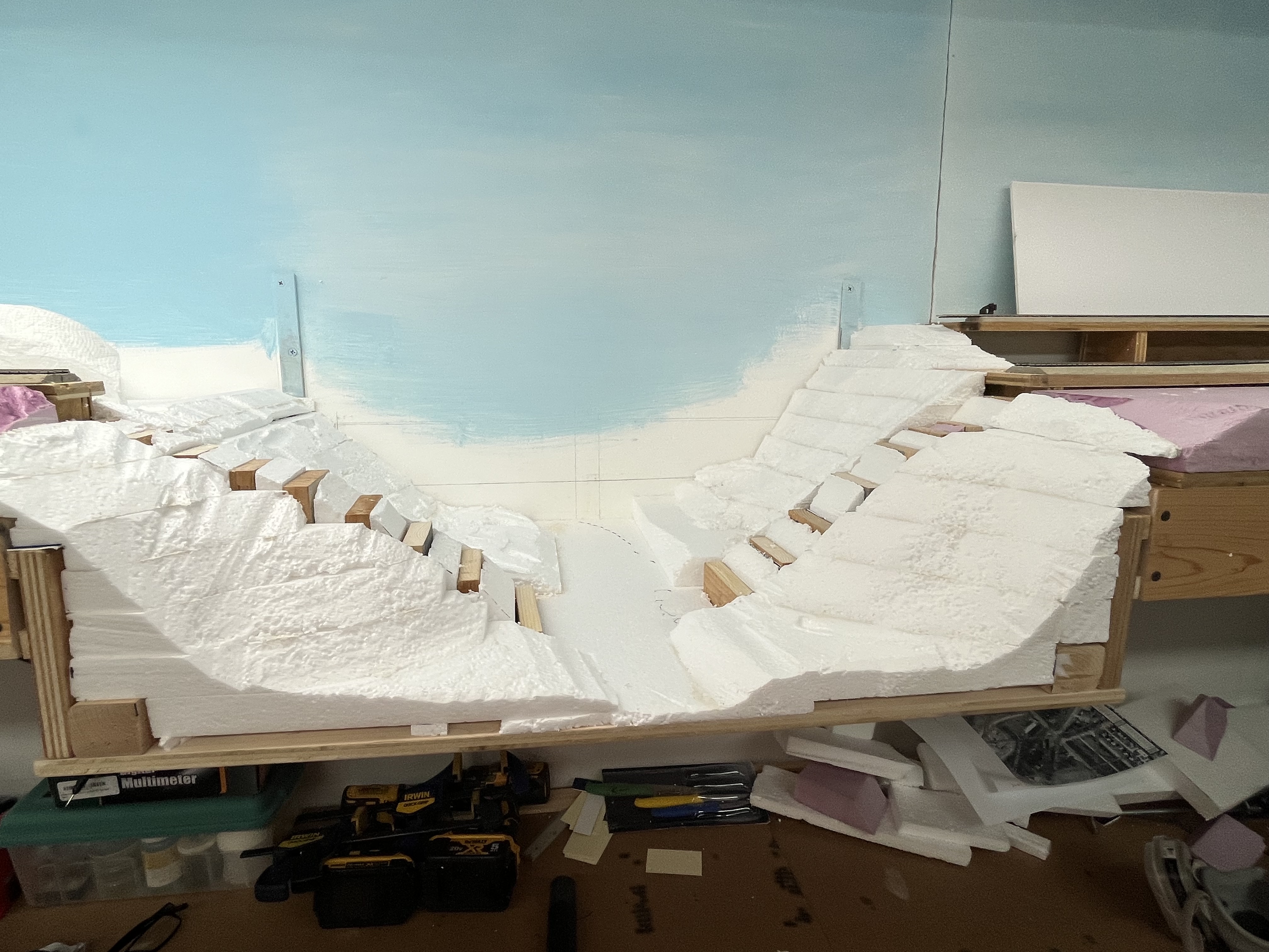
All of this will be covered with a layer of Sculptamold.
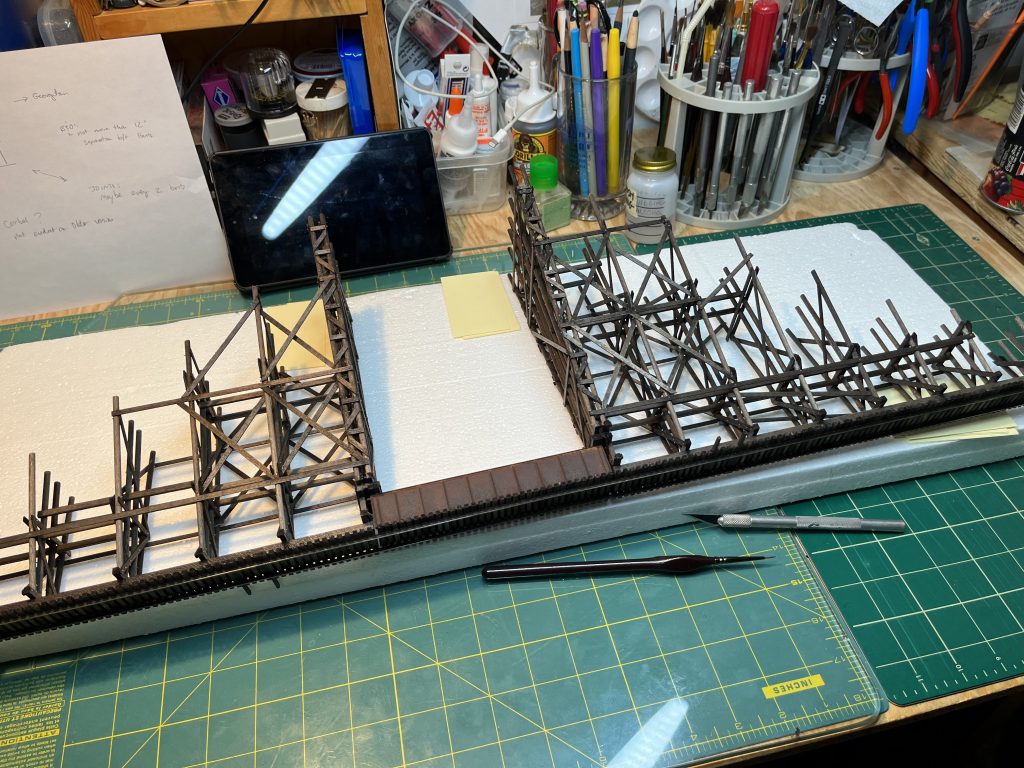
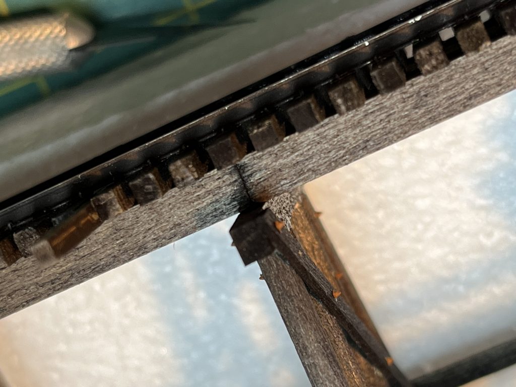
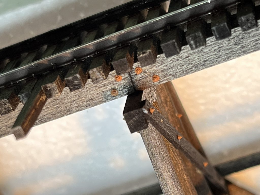
I also started on the final to-do’s on the trestle itself. I scribed lines in the sides of the stringers simulating the beams. I now will install NBW’s at each joint and above each bent. I need to put the stringers on the top of the trestle as well as build the little escape platforms. That will be last, as they stand proud of the top. After that, a little weathering and it will be time to install the trestle. Here’s a few more shots:
Other than this, not a lot going on last couple months. Saw my son off to college this week and work is busy! I picked up several new freight cars and have been doing research and planning on getting my fleet more rounded out – I realized this week that I am severely deficient in decent B&O 2-bay hopper cars.
I scored a copy of the wonderful Merchant’s Despatch book by Roger Hinman from Signature Press. I’ve had my eye on this for years and the price via the usual used book joints always dissuaded me. A random search turned up new copies for sale at Arizona Hobbies for $35! This is an excellent price and if you’re looking for this book, jump on it! I read the whole book when it arrived and enjoyed it tremendously.
Probably the biggest thing was I FINALLY was able to purchase the needed DCC Concepts Cobalt IP Digital turnout motors – these babies have been like hen’s teeth for the last several months due to manufacturer shortages. Iron Planet Hobbies stocked a few 12-pack cases and I picked up a couple, so now I am all set for turnout motors! (Side note, as of this writing Iron Planet Hobbies is again out of stock for the 12 and 6 packs. They have 17 single units in stock. They have had the BEST prices of any place I have found, so I highly recommend!) Need to figure out what I’m going to do for track in Georgetown (to hand-lay, or not to hand-lay!) but that’s a discussion for another day.
Oh, and one more thing. Here’s a sneak peek at something Kelly is cooking up:
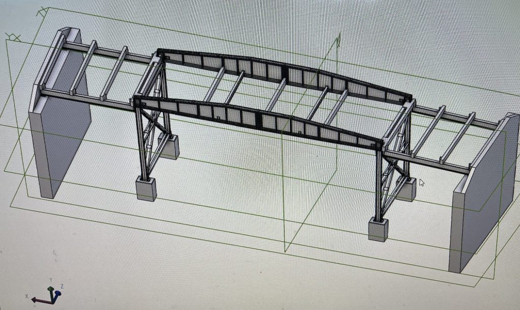
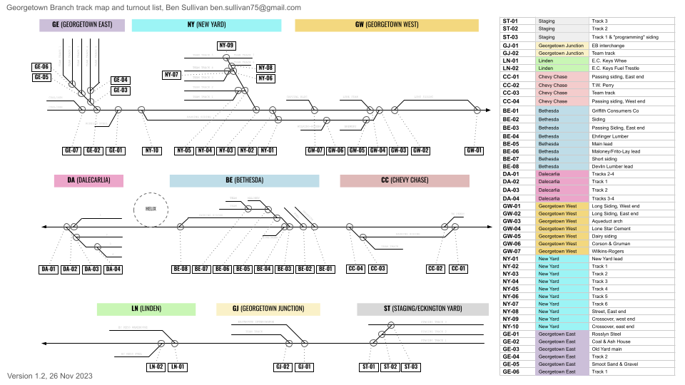
Georgetown Branch Track Chart and Turnout List
I spent a bit of time mocking up the layout track plan in Google Sheets and coupled that with my turnout list. This will be used as part of my wiring package to keep handy for troubleshooting and planning. Having the line drawing of the layout will also come in handy for operations planning and as I work toward my NMRA AP Dispatcher cert, I will build off of this diagram. Here’s a PNG (below) and a link to the original, on Google Sheets.
Layout Progress Update: June 19
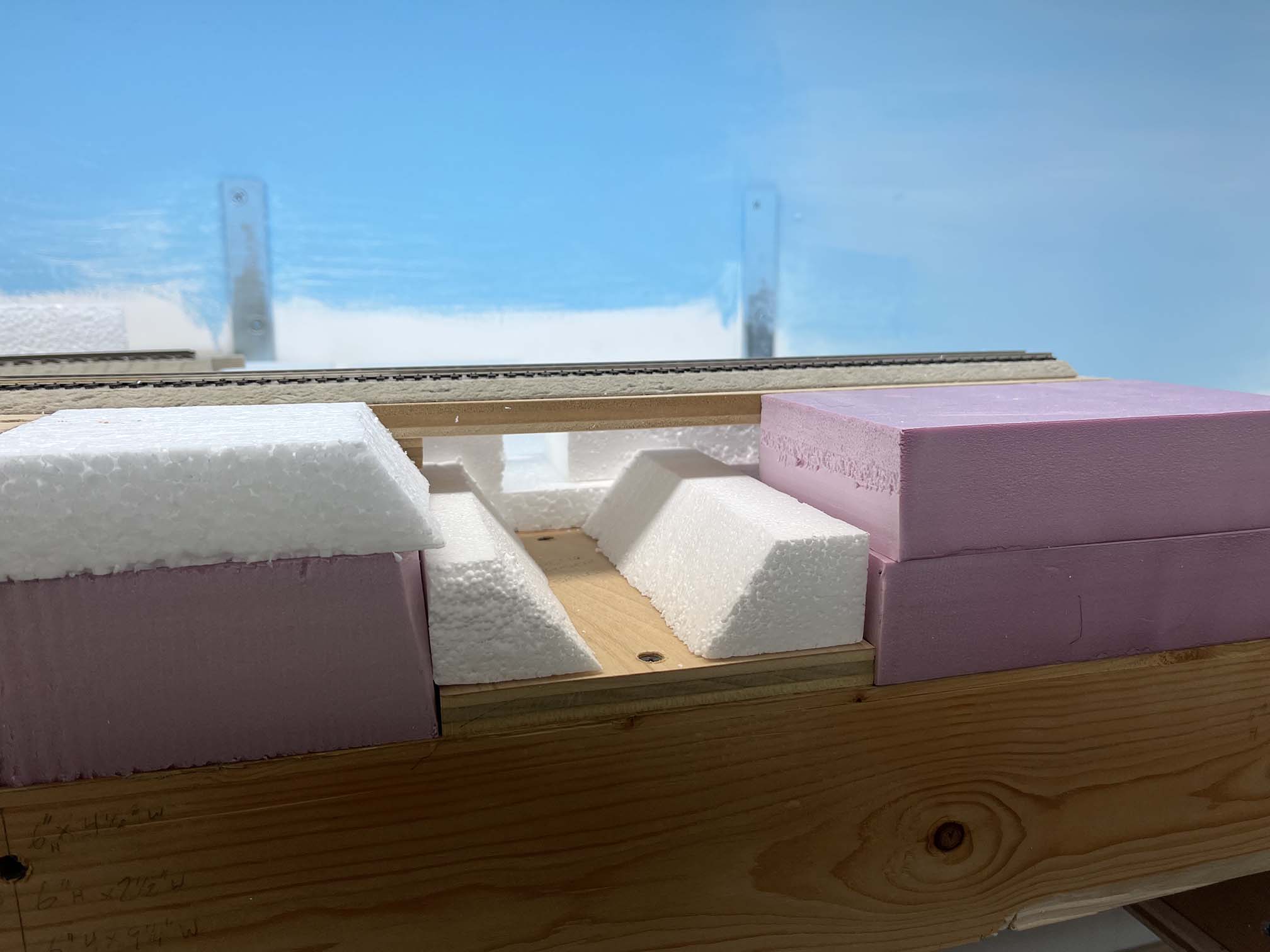
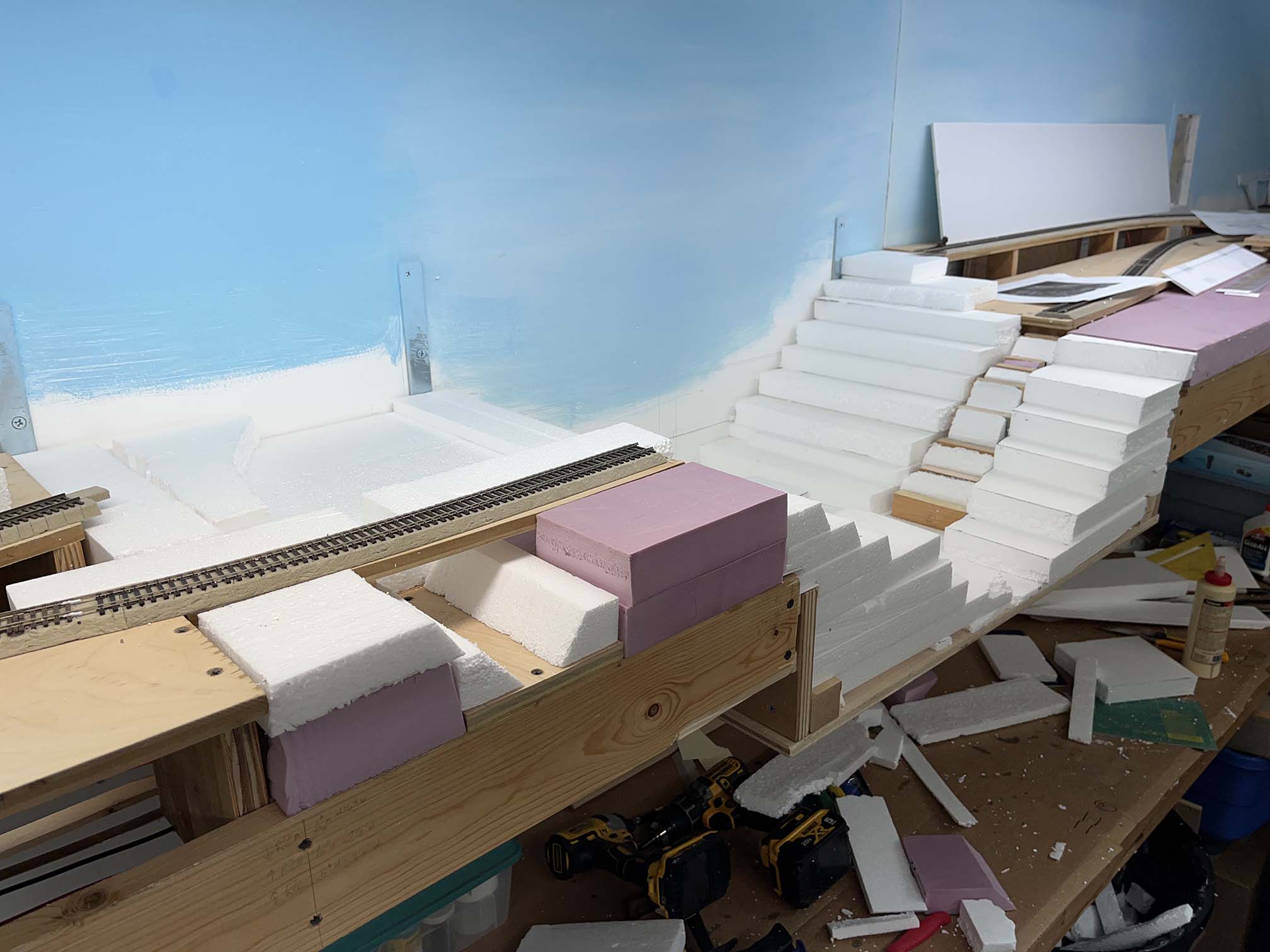
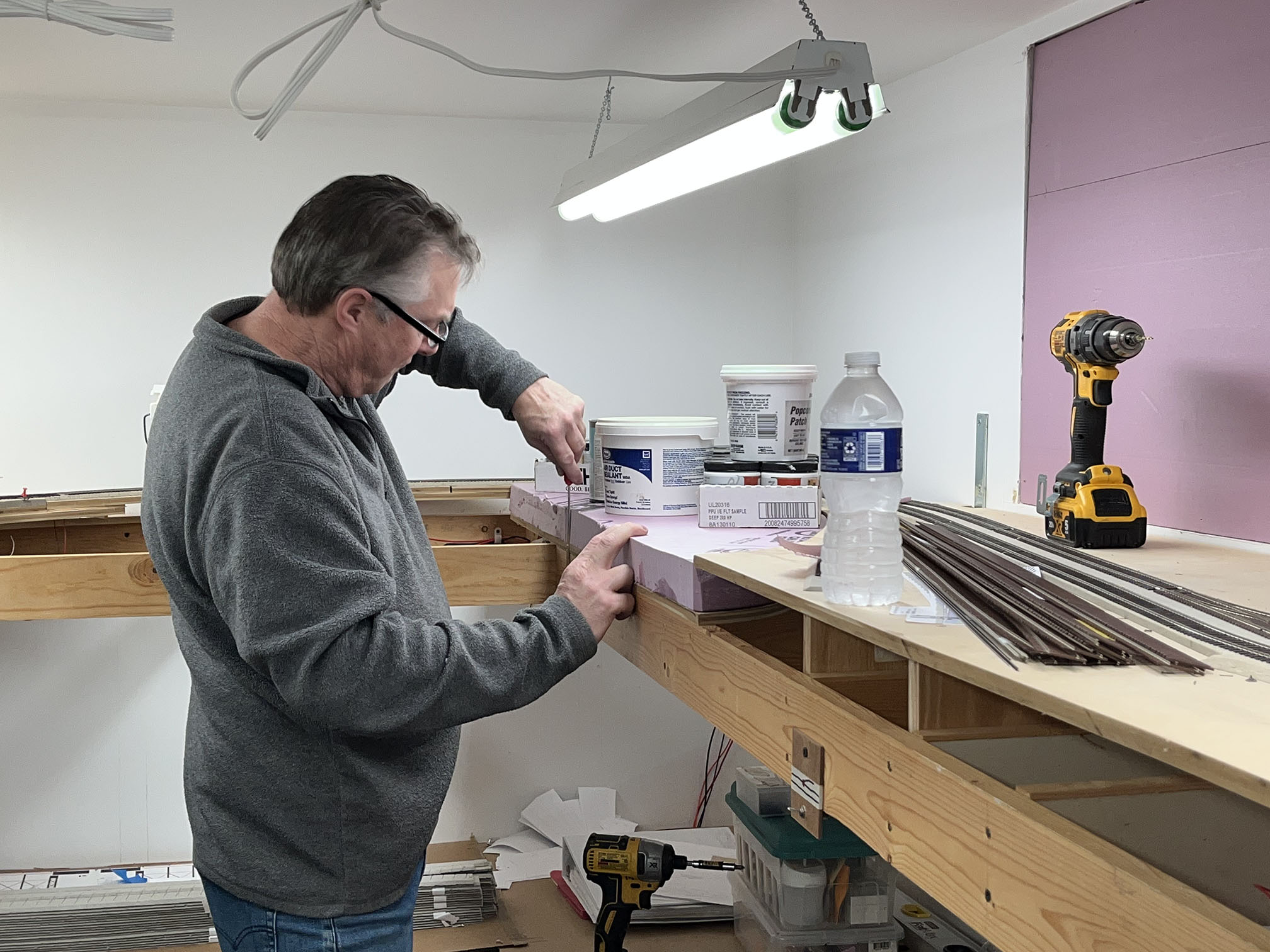
I spent a few hours working on the area around Rock Creek today and figured I’d throw an update on the blog. When my cousin Eric visited a few weeks back, he helped me get started on cutting and fitting Styrofoam to fit the area and flesh out the basic land forms.
Today I moved the project forward. First I spent a bit of time planning out the area near Chevy Chase. I decided that I could include the bridge next to T.W. Perry so I added a base for the feature. Here’s a couple prototype photos. It was hard to get a wide shot because there was a fence just behind me.
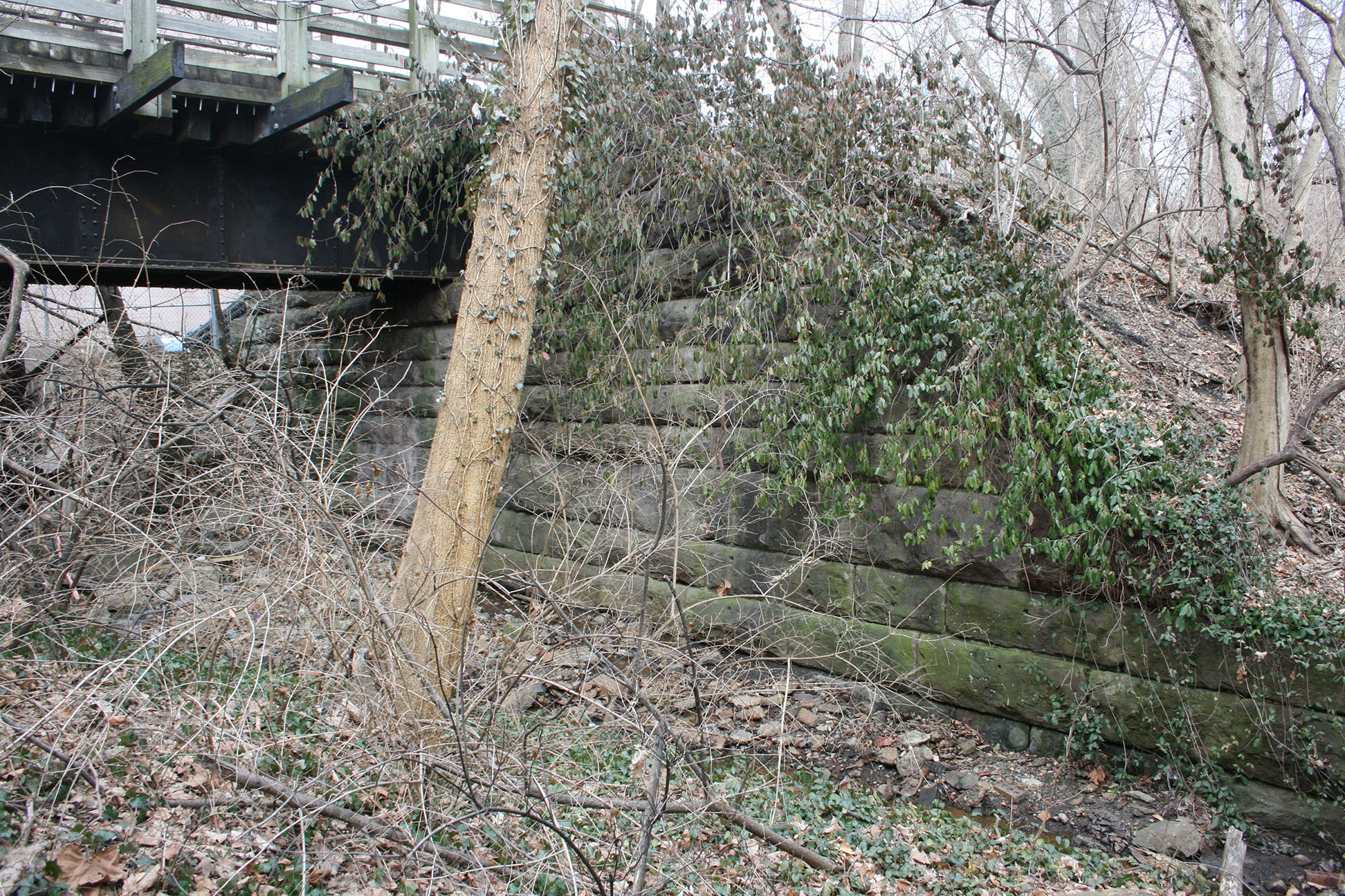
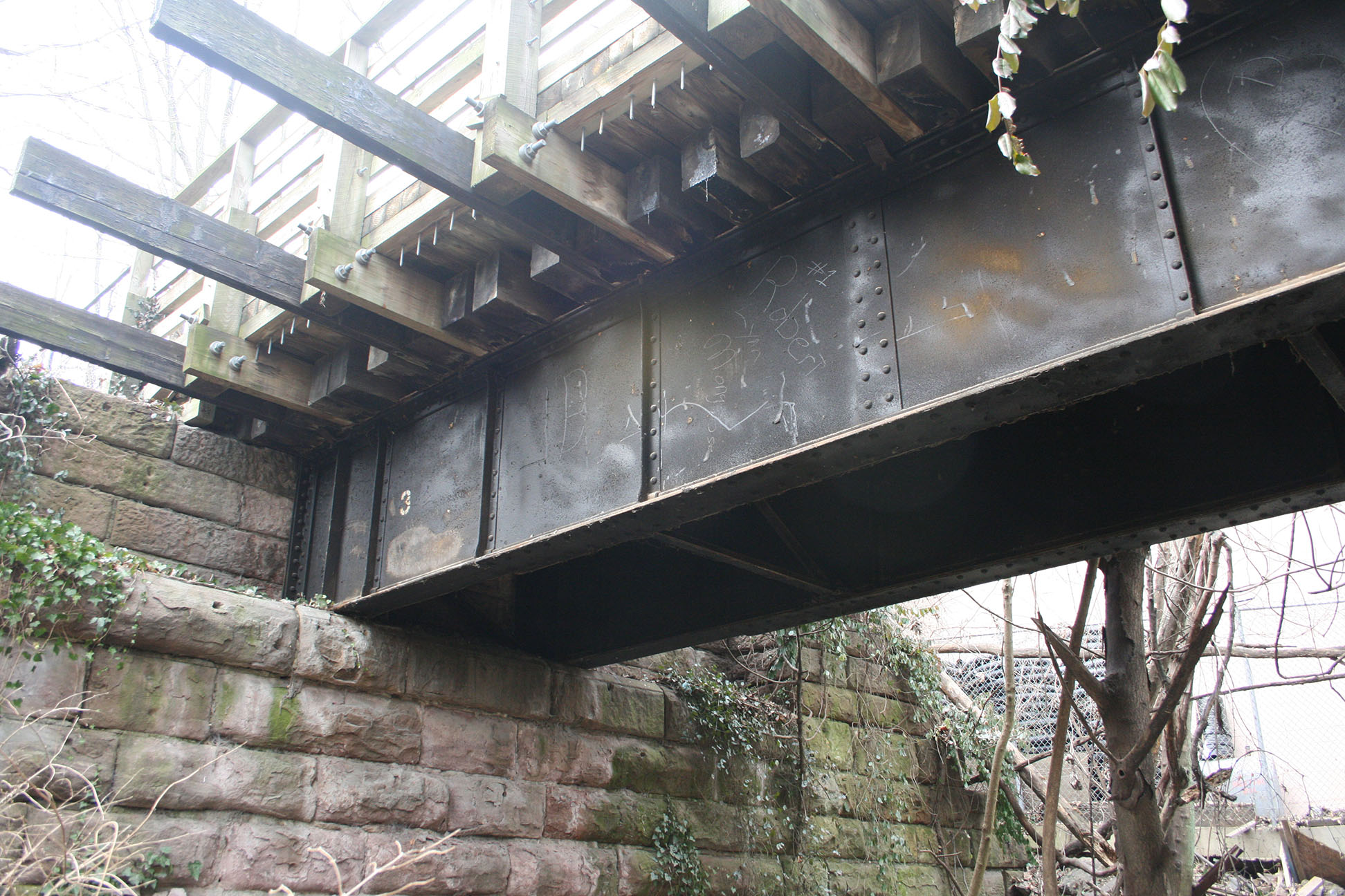
Oh, and sorry to say, this bridge was completely demolished in 2019 when the Purple Line construction passed through the area. 🙁 Anyway, here’s where it will fit on my layout:
Because the trestle is adjacent to the T.W. Perry scene, I had to work out both areas at the same time. So here’s some shots of how it all turned out:
Hope everyone is doing well and tackling their own model RR projects!
Layout Progress Update: May 2023
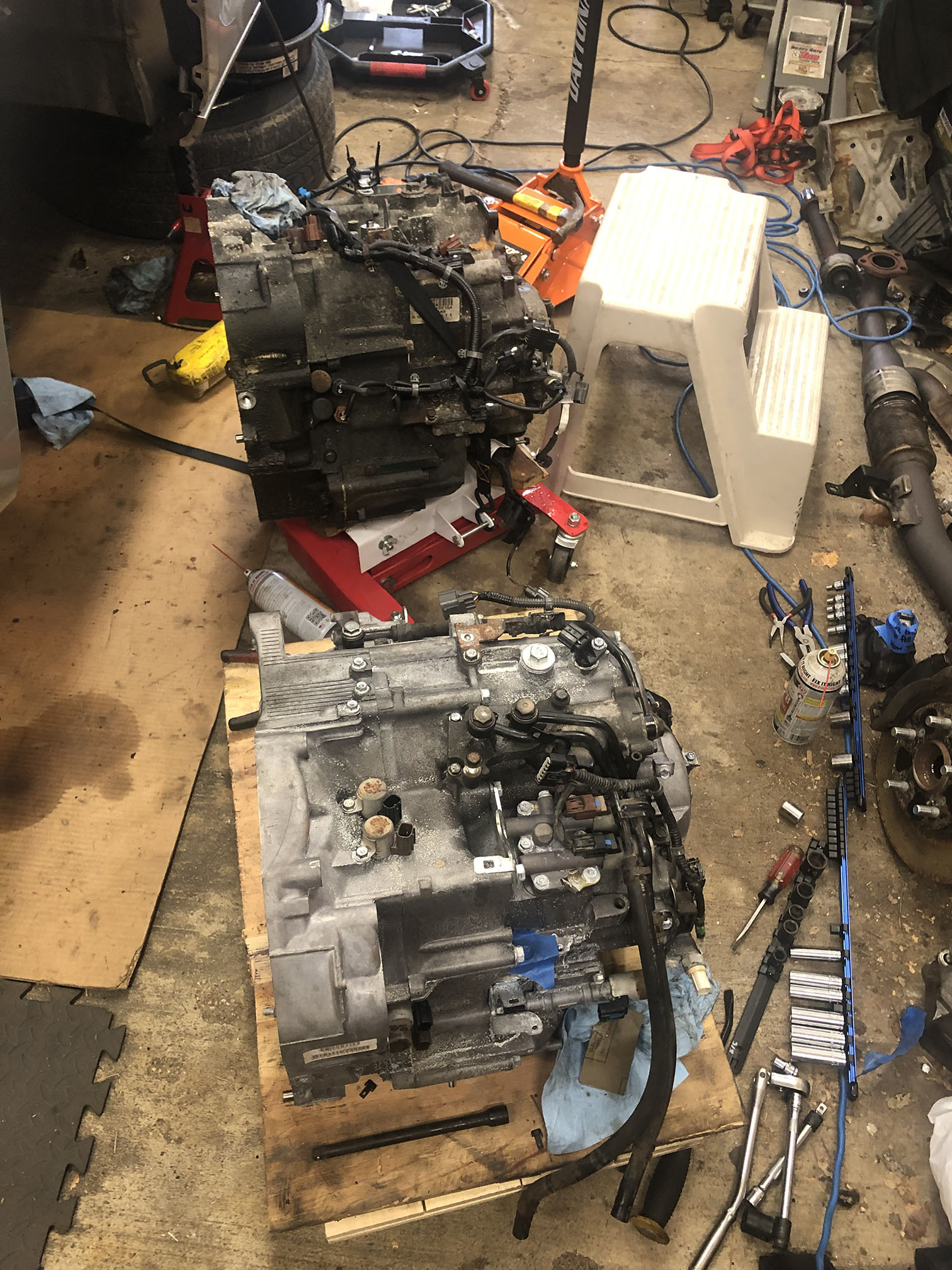
A quick update to share a few snapshots of some progress and talk about what has been going on since the Winter. Well, first up, between December and January I took on a massive project; replacing the transmission in my 2006 Honda Odyssey. The task was no small feat and I did nearly all of the work myself. As a result, I have a functioning car again, and have likely permanently damaged an already questionable right shoulder. (A recent MRI revealed the reality that surgery is likely in my future.)
But I digress. I showed you the Rock Creek trestle mocked up in place. Now let’s take a look at how I got there. I made the decision that building the trestle would be my priority. First up was to start mocking up the terrain to be sure it would work with the existing design. So I used some masking tape to outline the land forms.

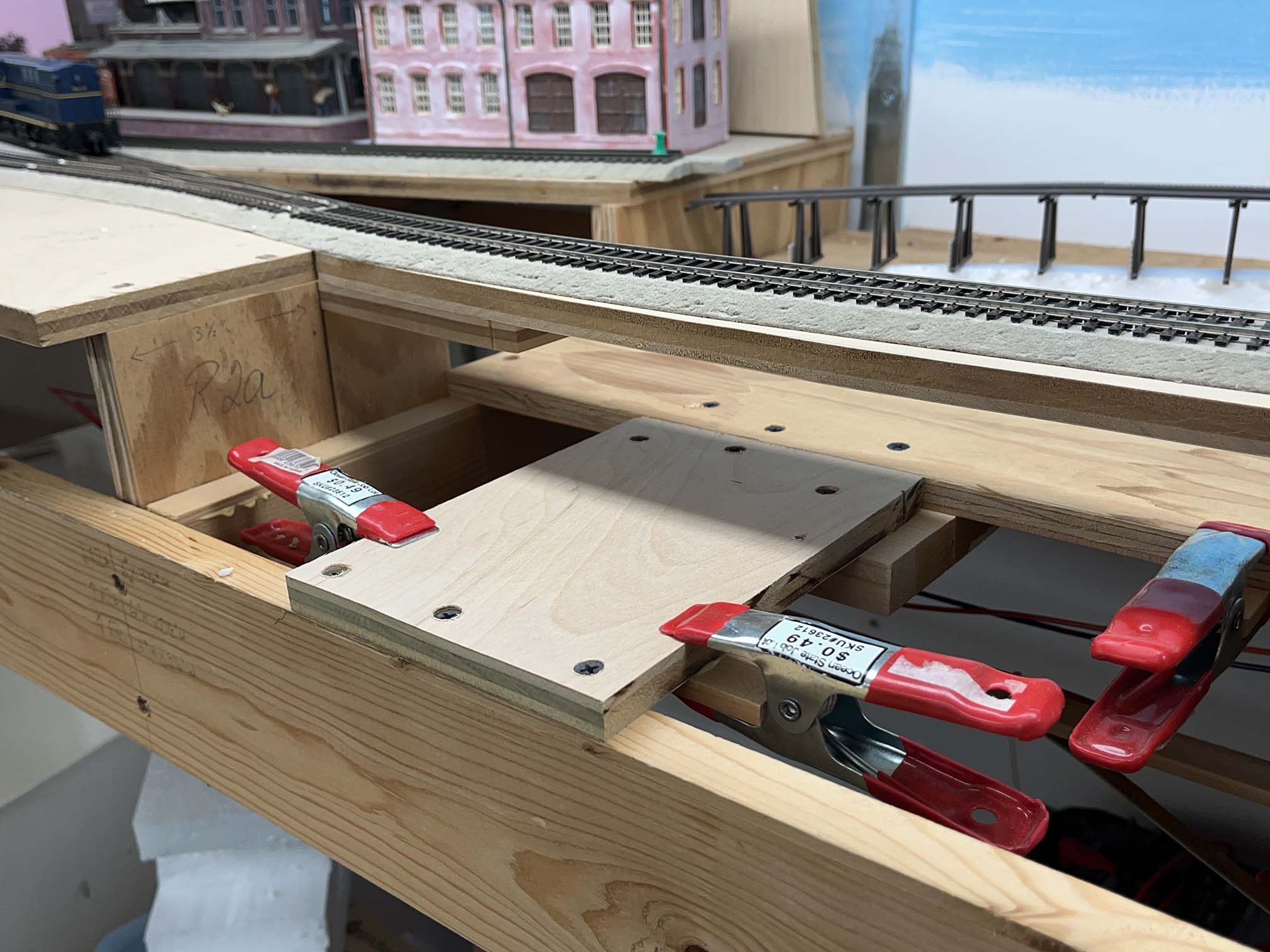
What became apparent was that the angle required for the long fill the trestle approaches sat on would not work with the existing benchwork. I also had the idea that it would be nice to be able to remove the trestle should I want to transport/save it from the layout room in the future. This required completely rebuilding this section of the layout, by essentially widening this dropdown area.
I then needed to install the trestle and shim it to sit flush and level with the track, so I could measure the height of each riser.
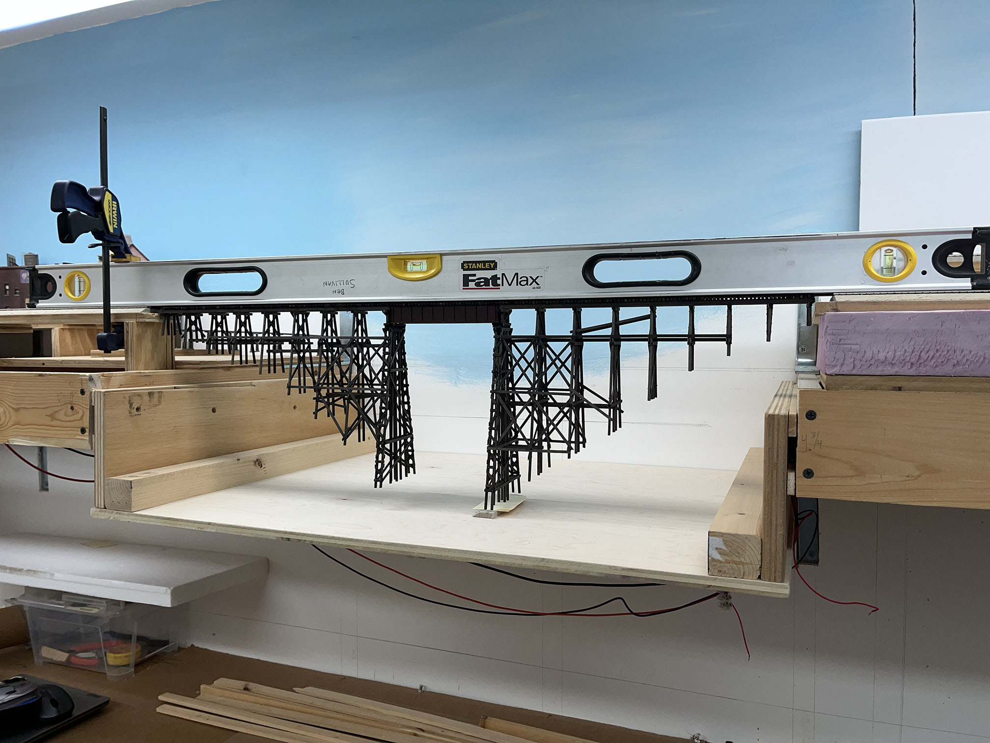
I measured the height from the base to the lowest pile in each bent. I subtracted about 1/16″ and fashioned risers from 1×4’s and other boards.
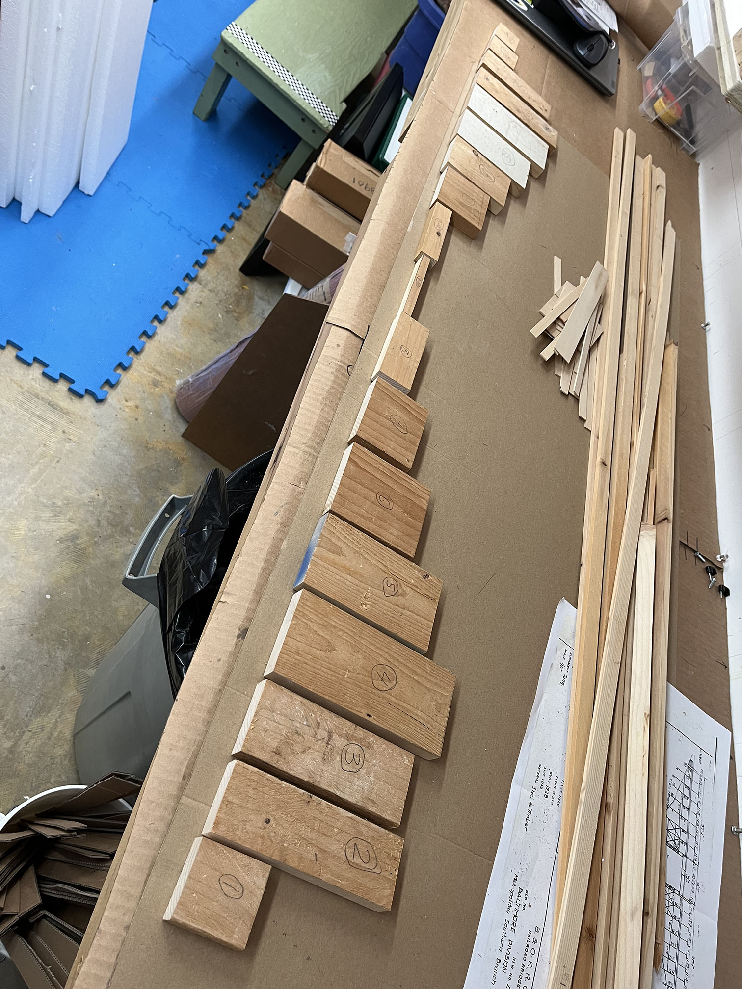
I installed the risers so the bent sits just on the edge. I will shim up to the height of each pile, since they are uneven. Risers were glued in place with wood glue.
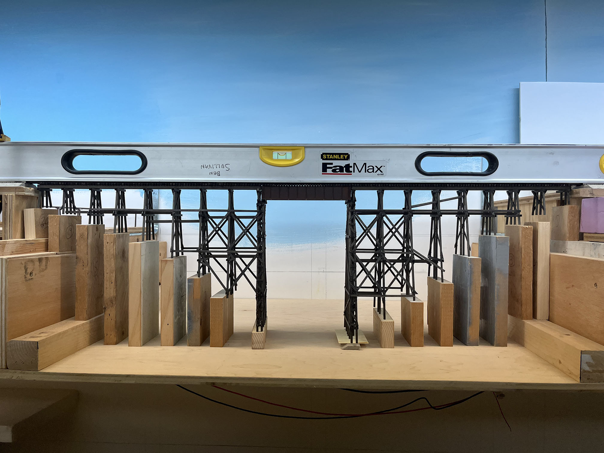
Now that the risers are in place, I can begin building the landforms, including the creek itself. I’ve still got a bit of work to be done on the bridge; namely the stringers on the top deck and some other details, but otherwise I’m nearly done. The same day I worked on the new benchwork, Kelly came over and helped me figure out and install the new benchwork as well as some foam at Chevy Chase and at Georgetown Jct. Progress!
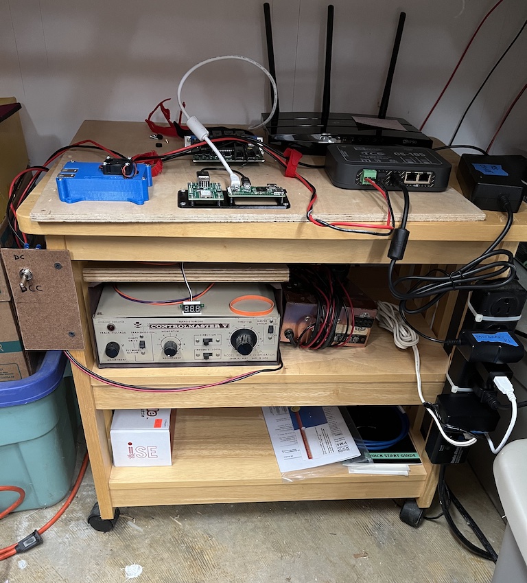
A few other command system and lighting improvements: I deaccessioned myself from the old Digitrax Empire Builder II system and picked up a new TCS CS-105 unit.

After a weekend of setup, it is functioning beautifully.
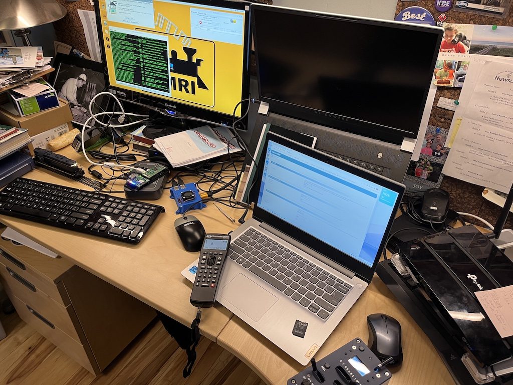
With the addition of my trusty RasPi/JMRI, the ProtoThrottle is working well, too.
I also installed LED strip lights beneath the upper deck on half of the layout.

This is very much a work in progress as I attempt to best engineer how to get the most out of them, but I am really pleased with the initial setup. More to come on this later.

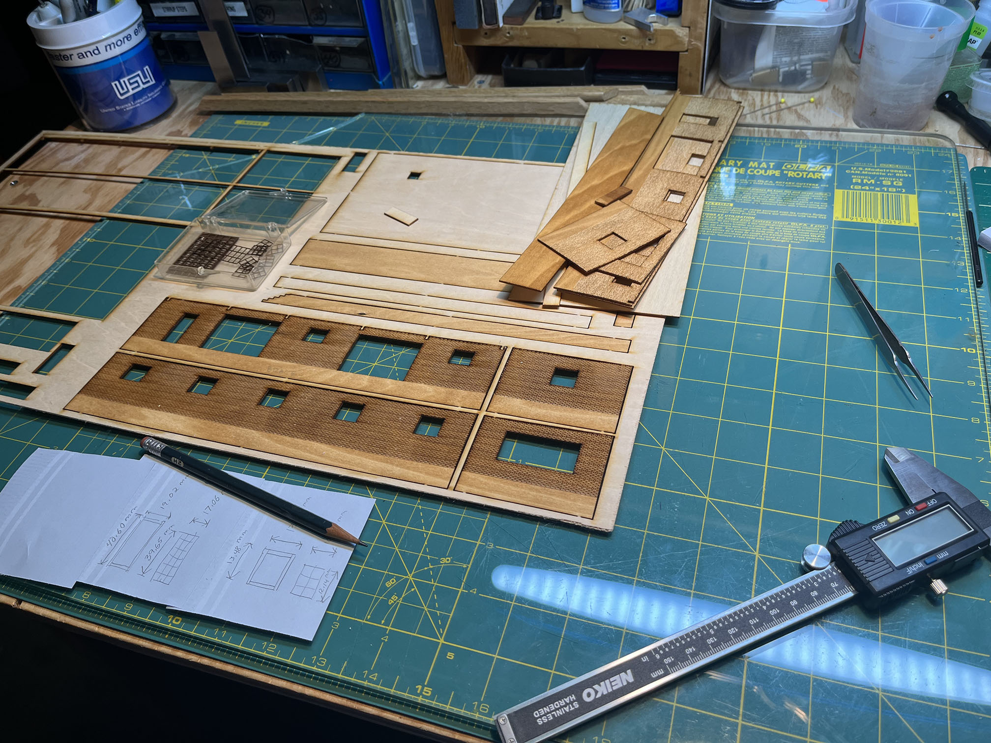
I’ve also been giving some thought to completing my model of the Bethesda Freight House. If you recall, a few years back I designed and laser-cut parts for my model of the station, but hadn’t assembled it. I spoke with Greg C. who is a master at building structures, about how to proceed and he gave me some great tips. I need to figure out the inserts for some of the moulding around various windows and engineer how I will install the garage doors, and get building.
Well, that’s all for now. Life is quite busy at the moment; my kids are wrapping up the school year, lots of sports activities, road trips, and other commitments. I’m taking a week off to host my cousin and we are planning on hitting several regional railfan spots, hobby shops and working on my layout. Hopefully more progress reports soon!
Scale Wheel Stops Video Short
Recently friend of the blog, Greg Cassidy, did a YouTube Short on Kelly’s magnificent 3D printed HO scale wheel stops based on the prototype. Have a watch:
https://youtube.com/shorts/hurWsa3R4_Y?feature=share
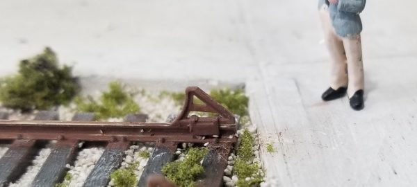
A few years ago I was lamenting to Kelly how there were no good HO scale wheel stops on the market. Nearly all of them look chunky and oversized. (because they are.) We visited a stretch of abandoned Georgetown Branch right of way in Bethesda where a siding still exists that includes original wheel stops. Kelly was inspired to draw up a model in Fusion360 and printed a few test items before developing a final design. Here are a couple in place on his layout:
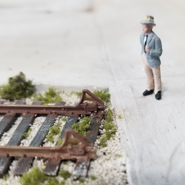
They are simply the finest wheel stops on the market, full stop. (pun intended.) They are 3D printed in resin, are quite durable, easy to install and if they break, you can simply glue another one on. Kelly sells them over on his site, FineScale360. Get a few for your own layout!
Upcoming Project: TCS CS-105 and LED Lighting for the Lower Level
I took the plunge and decided to rid myself of my twenty-some year old hand-me-down Digitrax Empire Builder II starter set for something a bit more cutting edge. I really like what TCS is doing these days with their new systems and was able to finally see one in action at Springfield last winter. A new CS-105 is on hand and will be installed soon.

I also picked up a handful of LED light strips and a power supply. These will be used to illuminate the lower deck. Hope to do a full write up on this once installed. Need so cut some 1/8″ strips to mount the lights to.
