I know I haven’t posted in a while but as the Spring approaches, things are getting busy around here. Work has been nuts. HPDE season is upon us and I’ve got my first event at Summit Point with the Audi Club this coming weekend. Track prep time! Here’s the update:
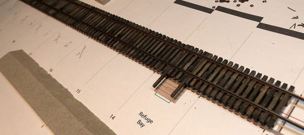
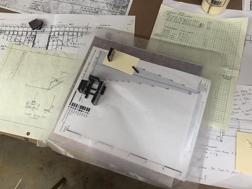
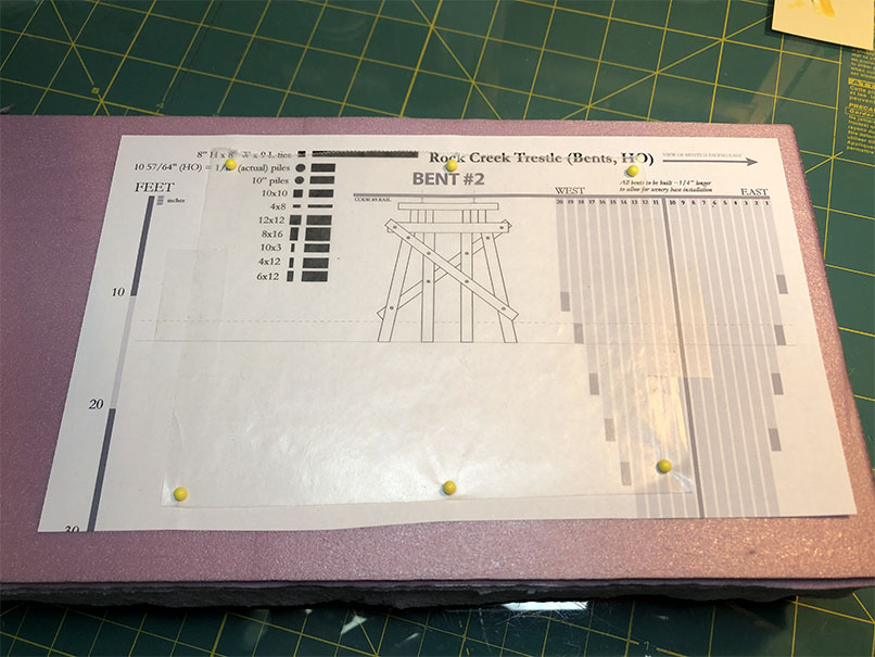
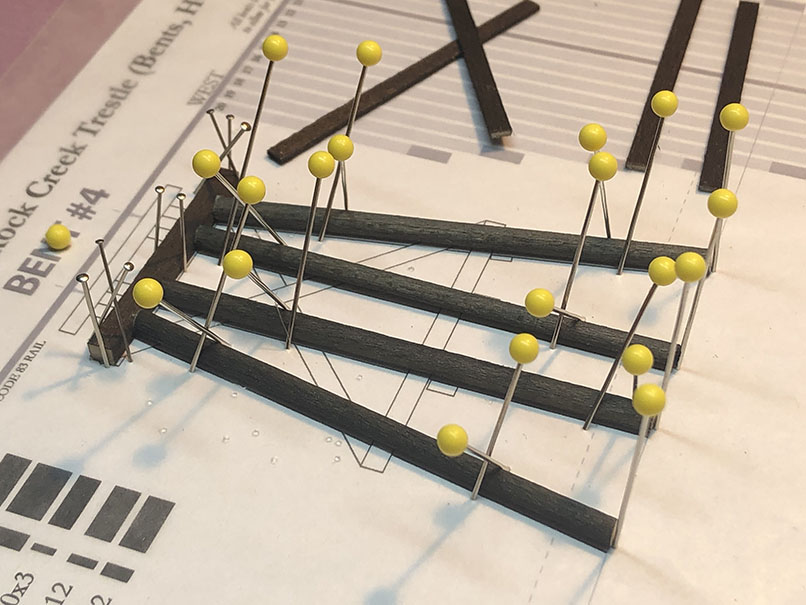
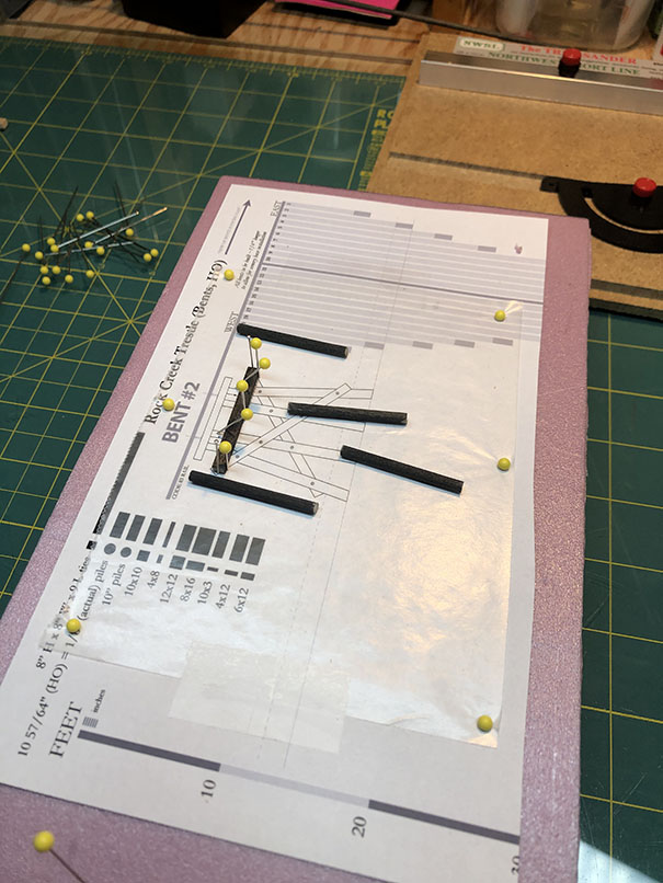
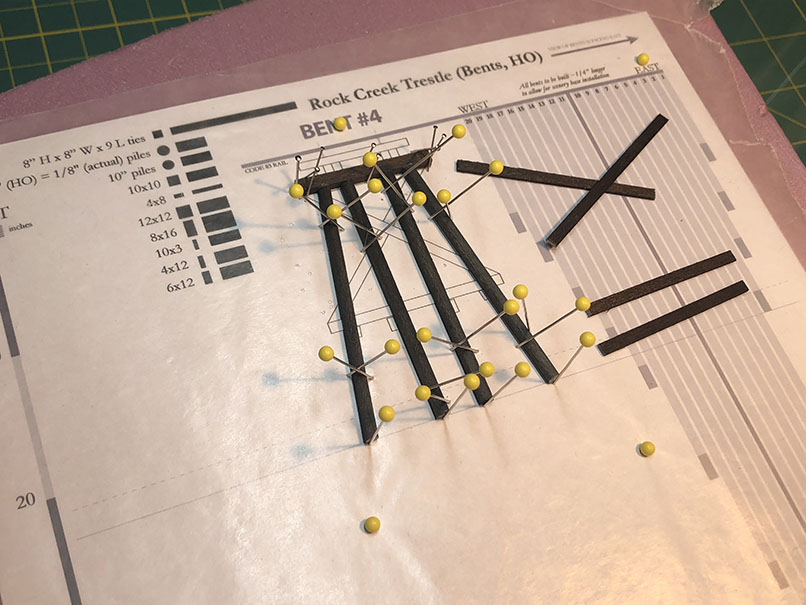
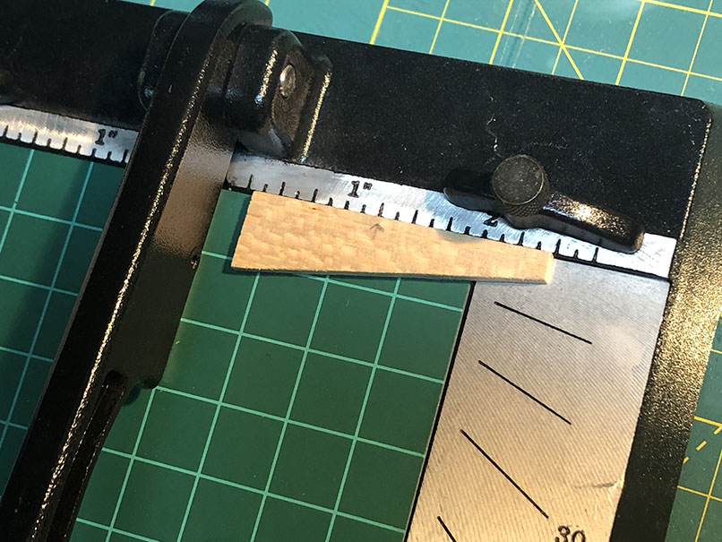
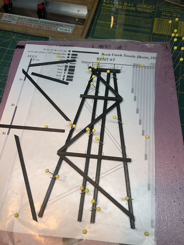
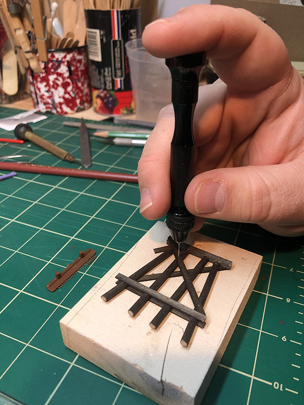
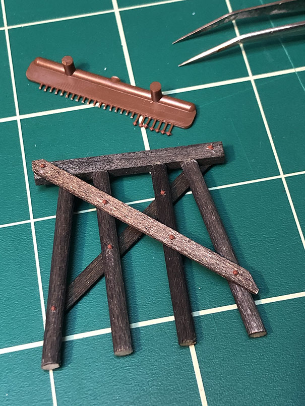
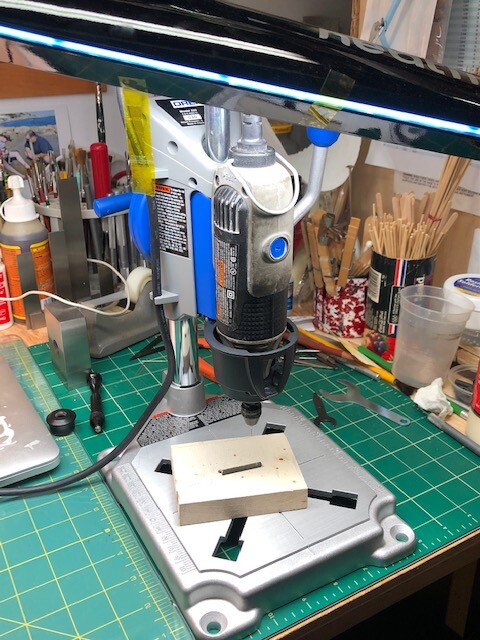
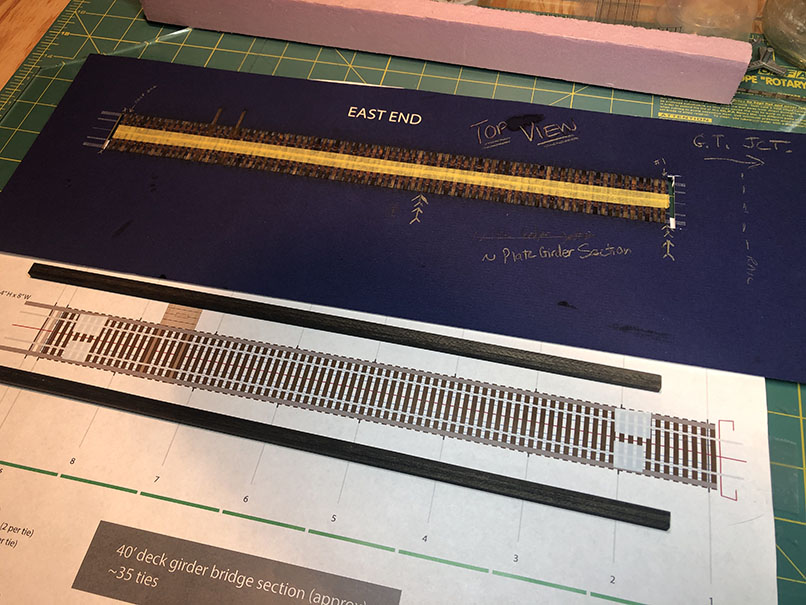
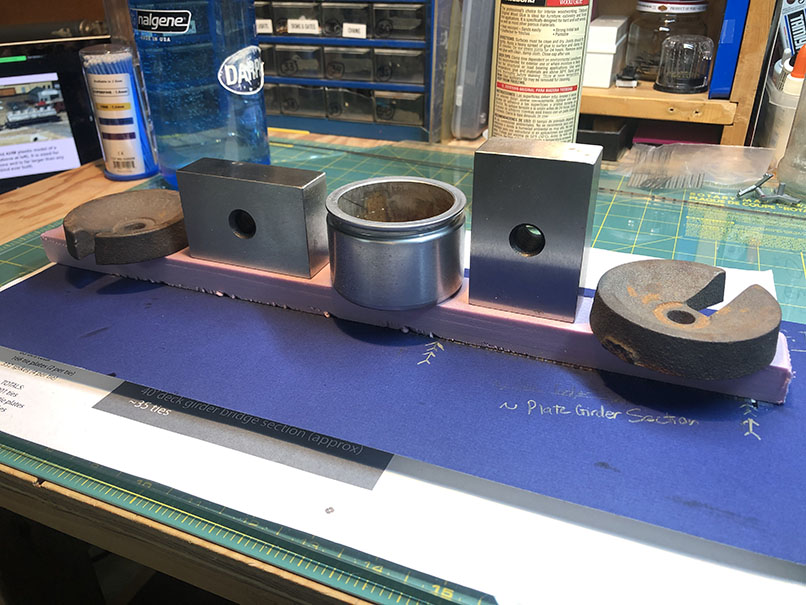
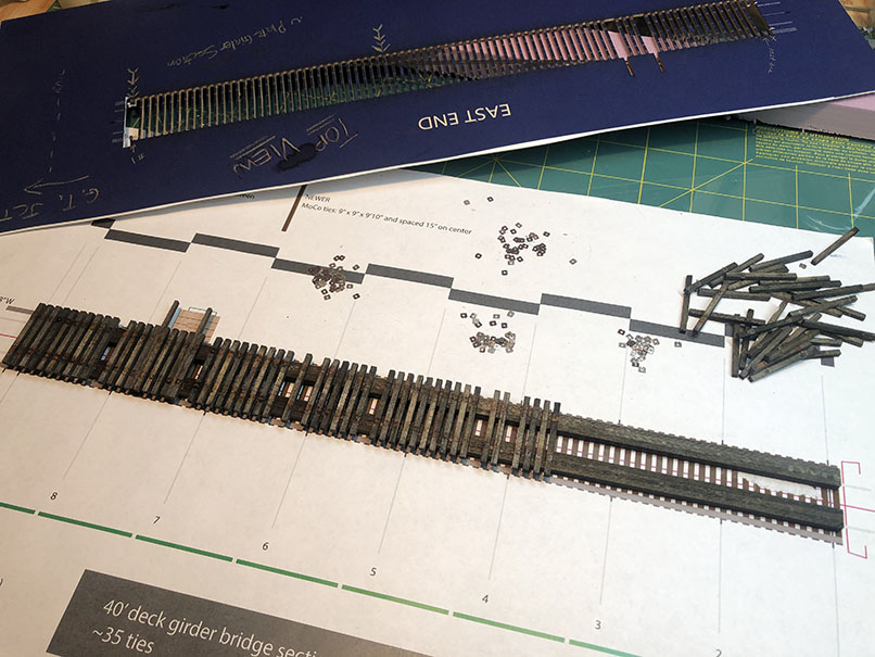
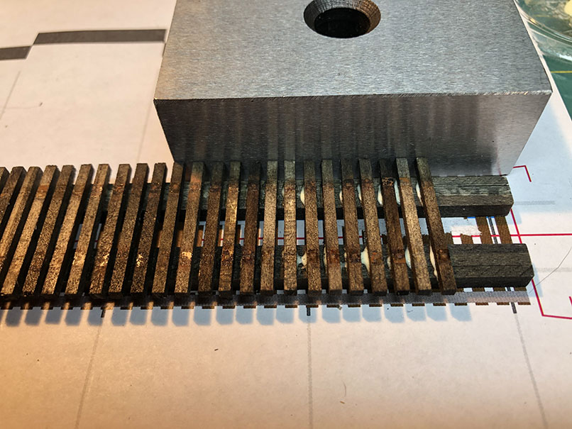
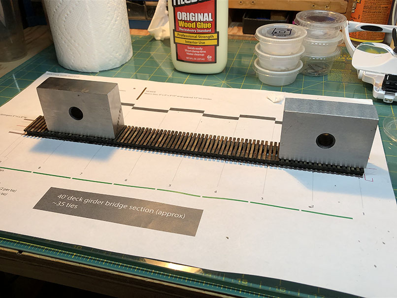
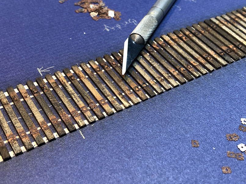
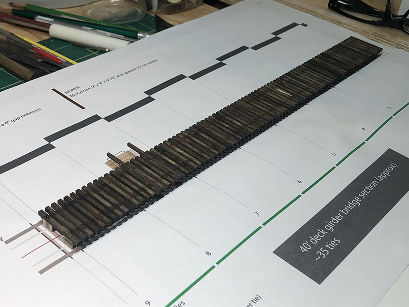
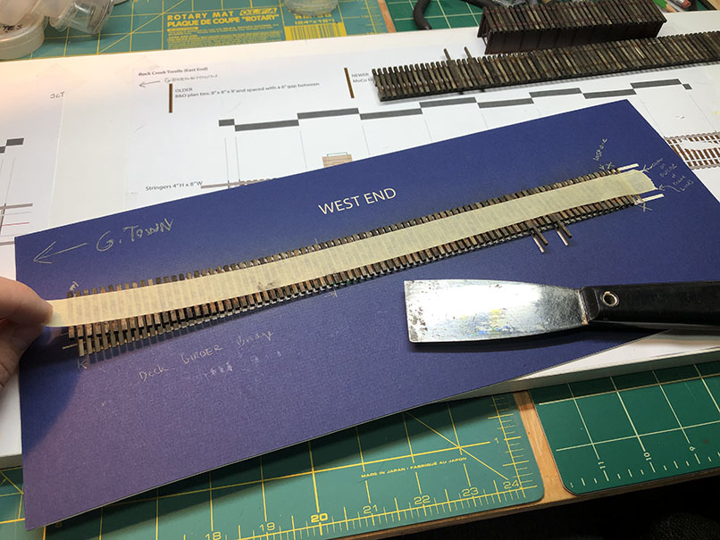
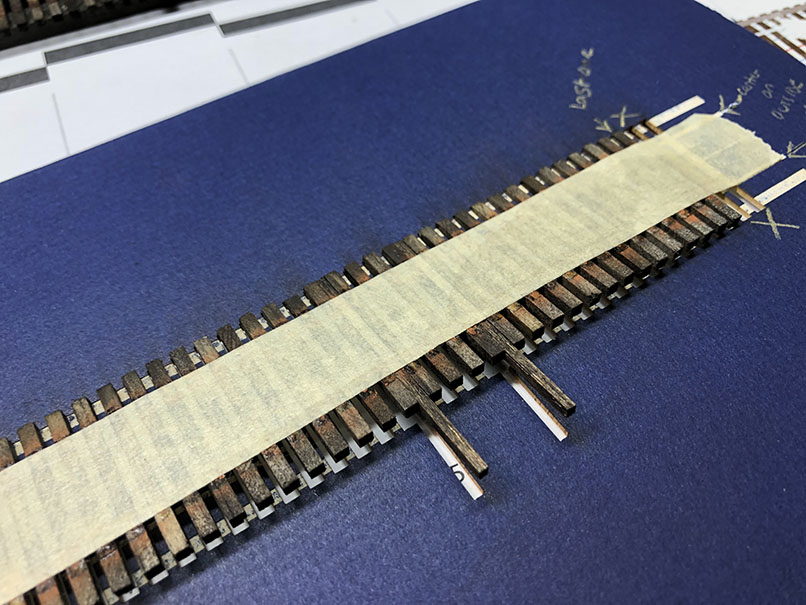
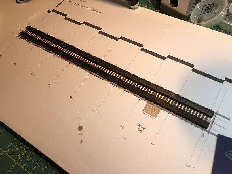
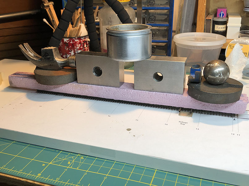
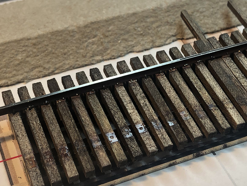
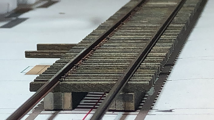
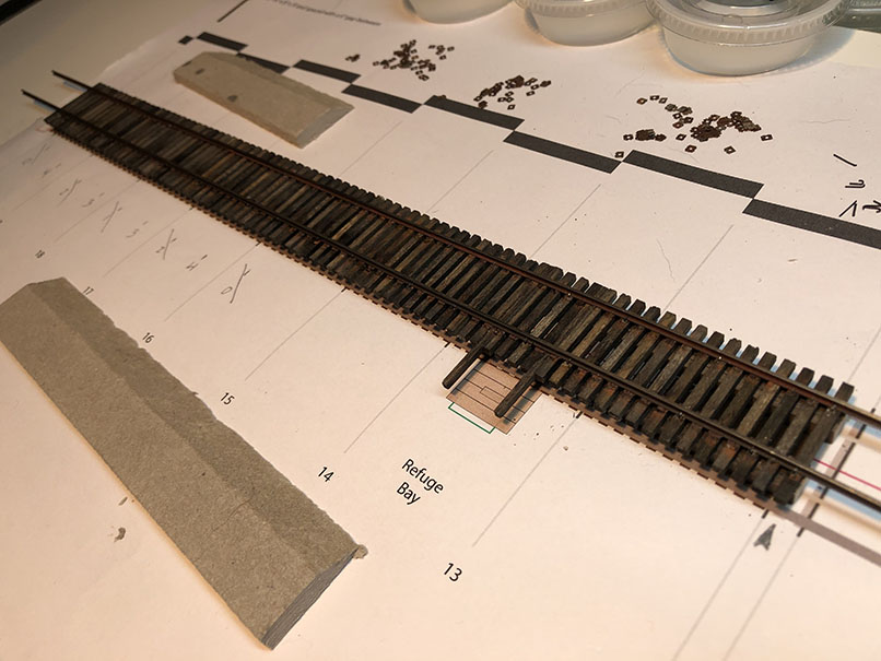
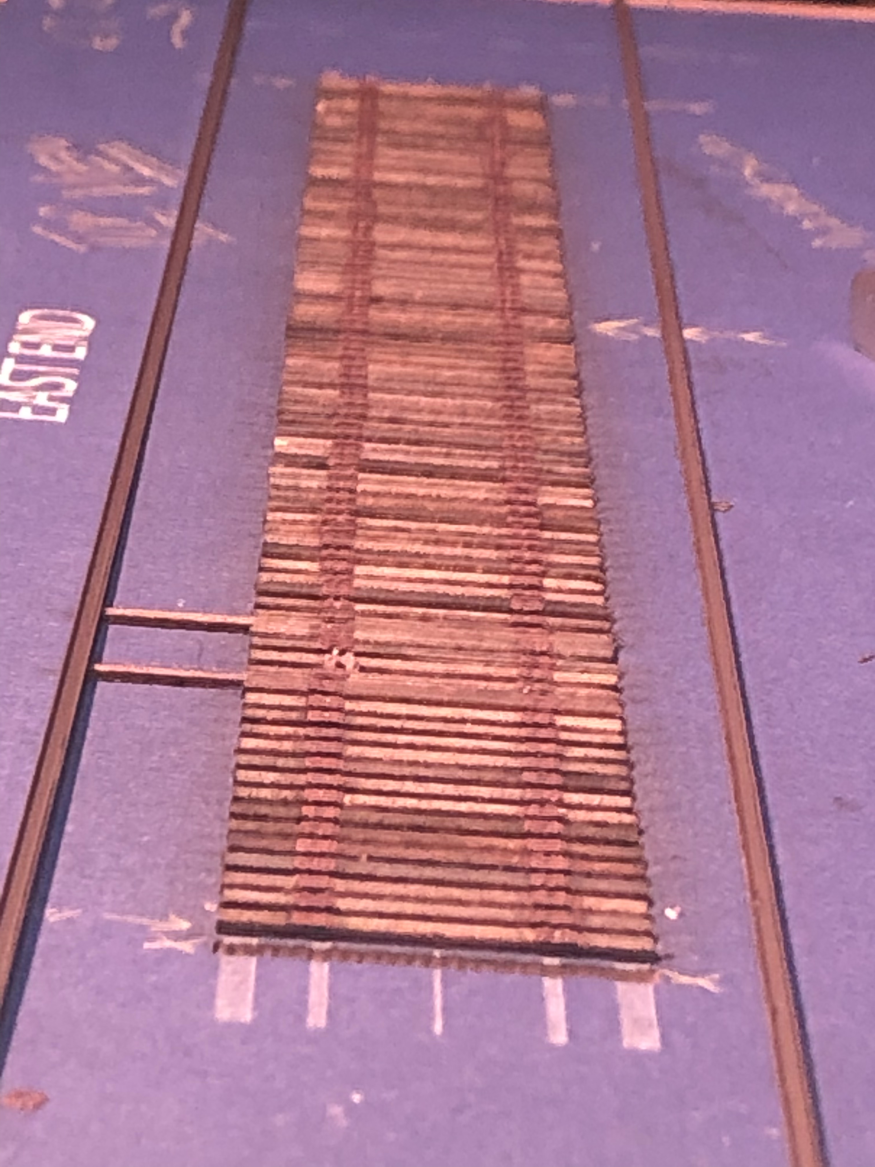
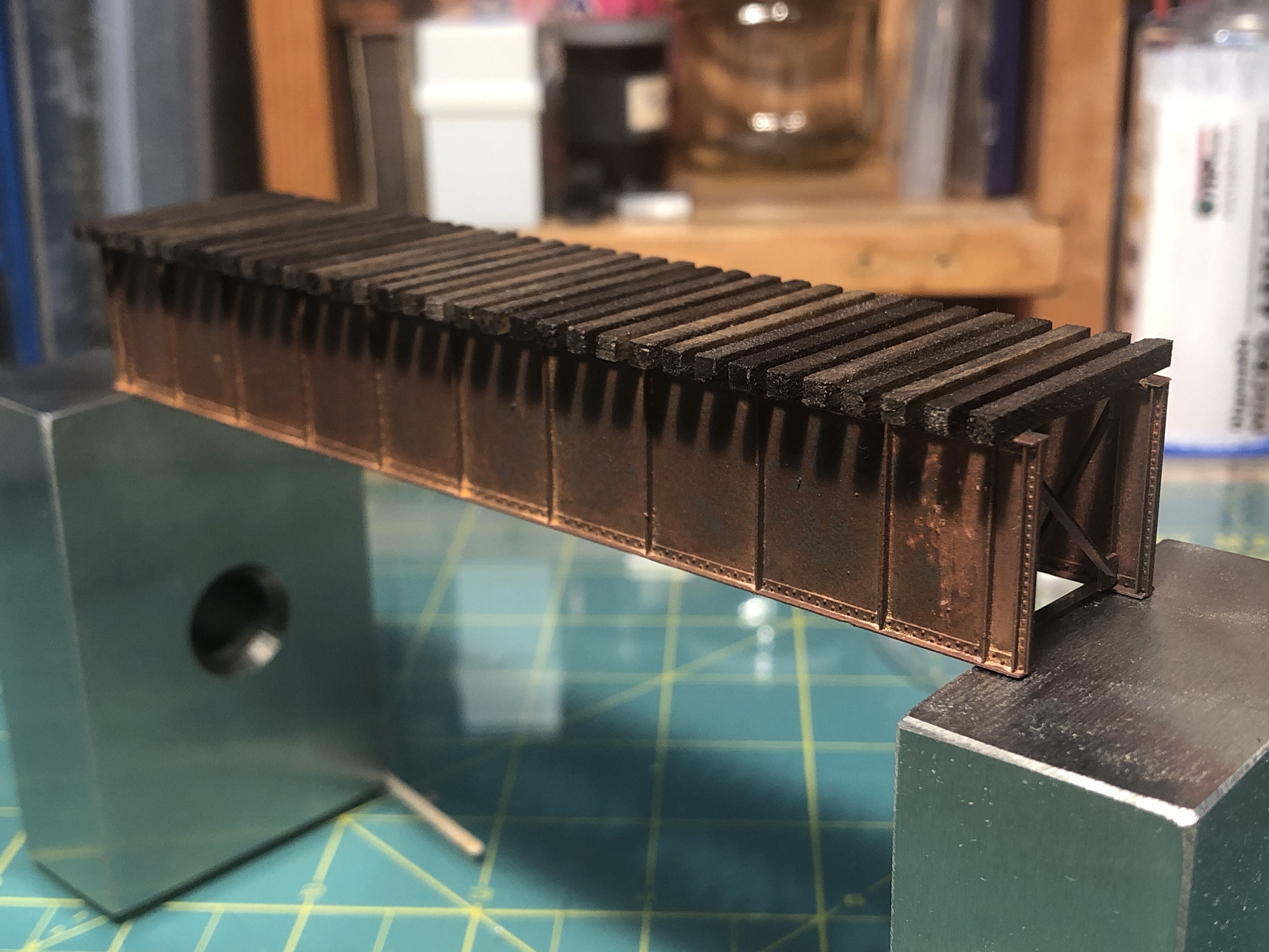
Layout progress has been focused on cleaning up, organizing and working on the Rock Creek trestle, as well as devoting a large amount of time to working out the operations scheme in JMRI Operations Pro, with lots of help from Kelly R. The cleaning and organization tasks were accelerated by a visit from Ken & Bill from Spring Mills Depot. Ken and I chatted at the Springfield show and decided to get together to see each others’ layouts and share progress and lessons learned. It’s been very motivational seeing what Ken is doing and having them visit my layout to talk about my own process and future goals. I’ve got lots of good energy to move forward with.
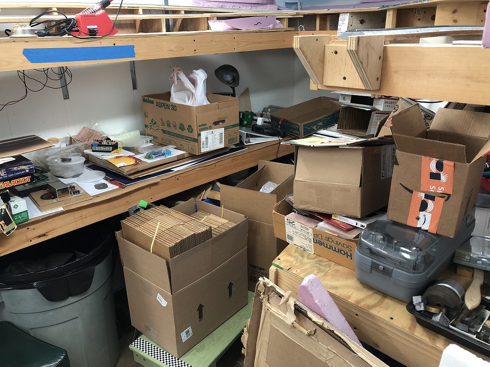
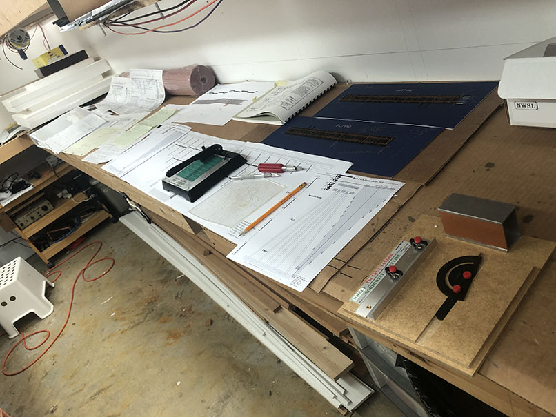
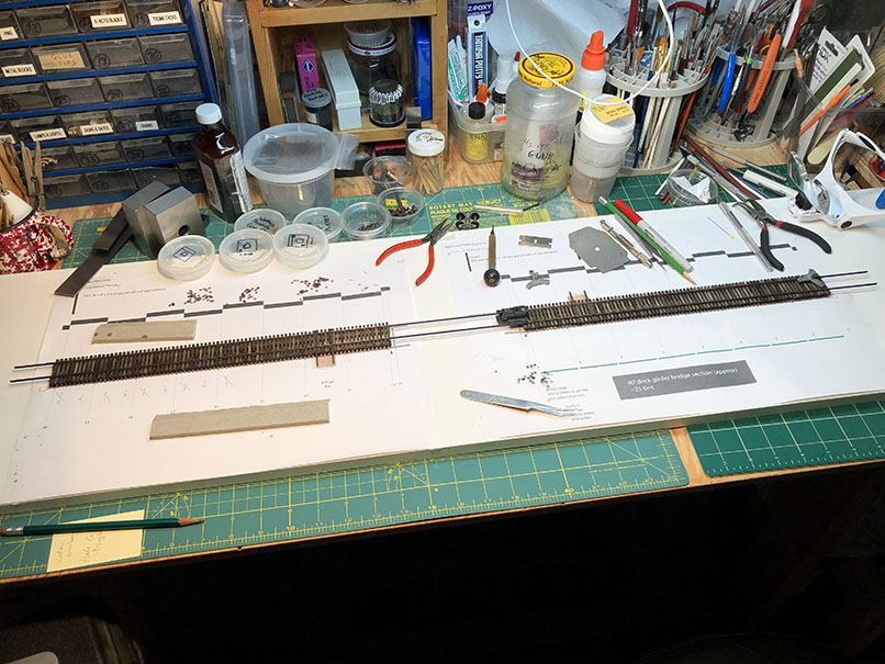
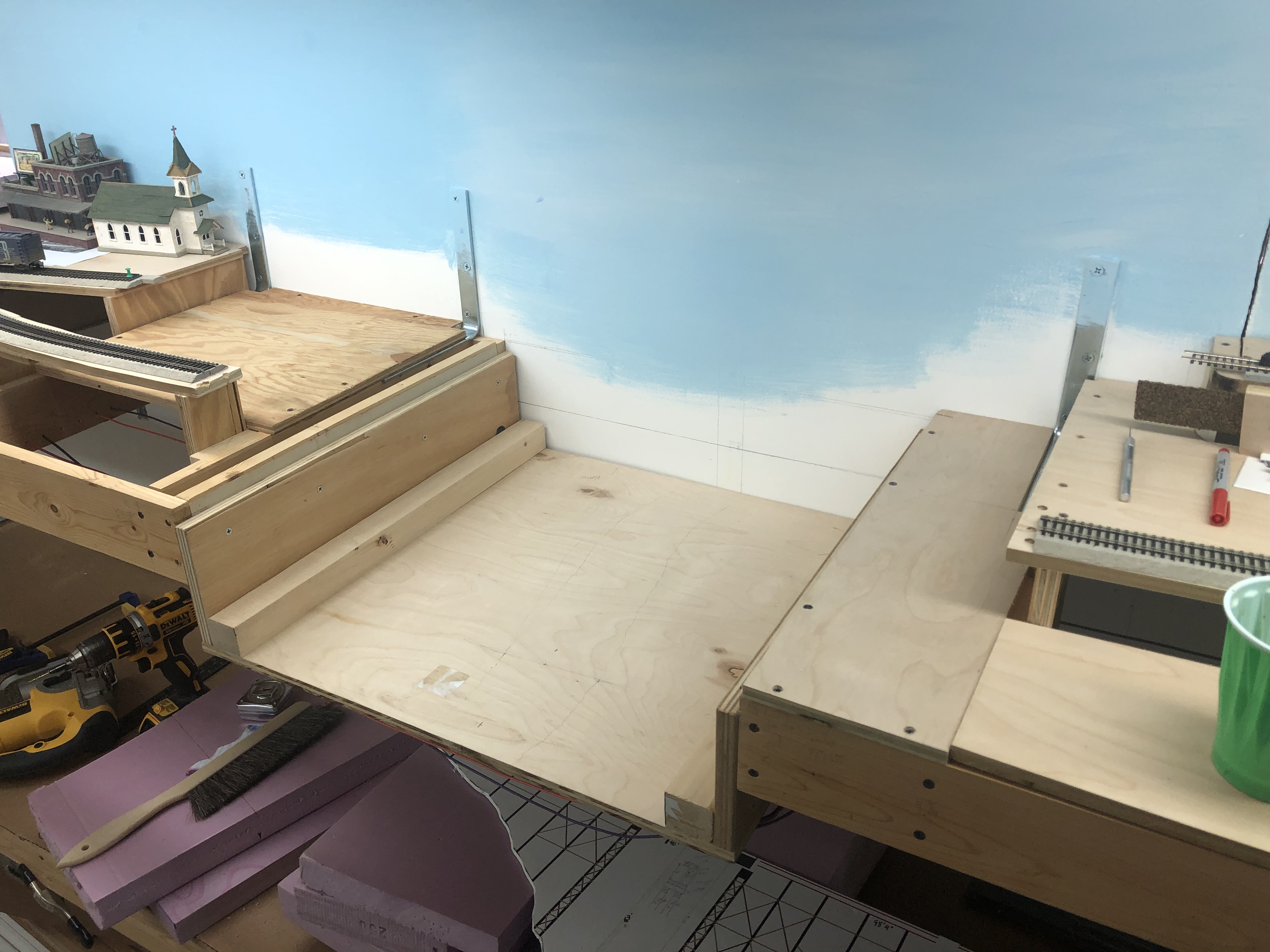
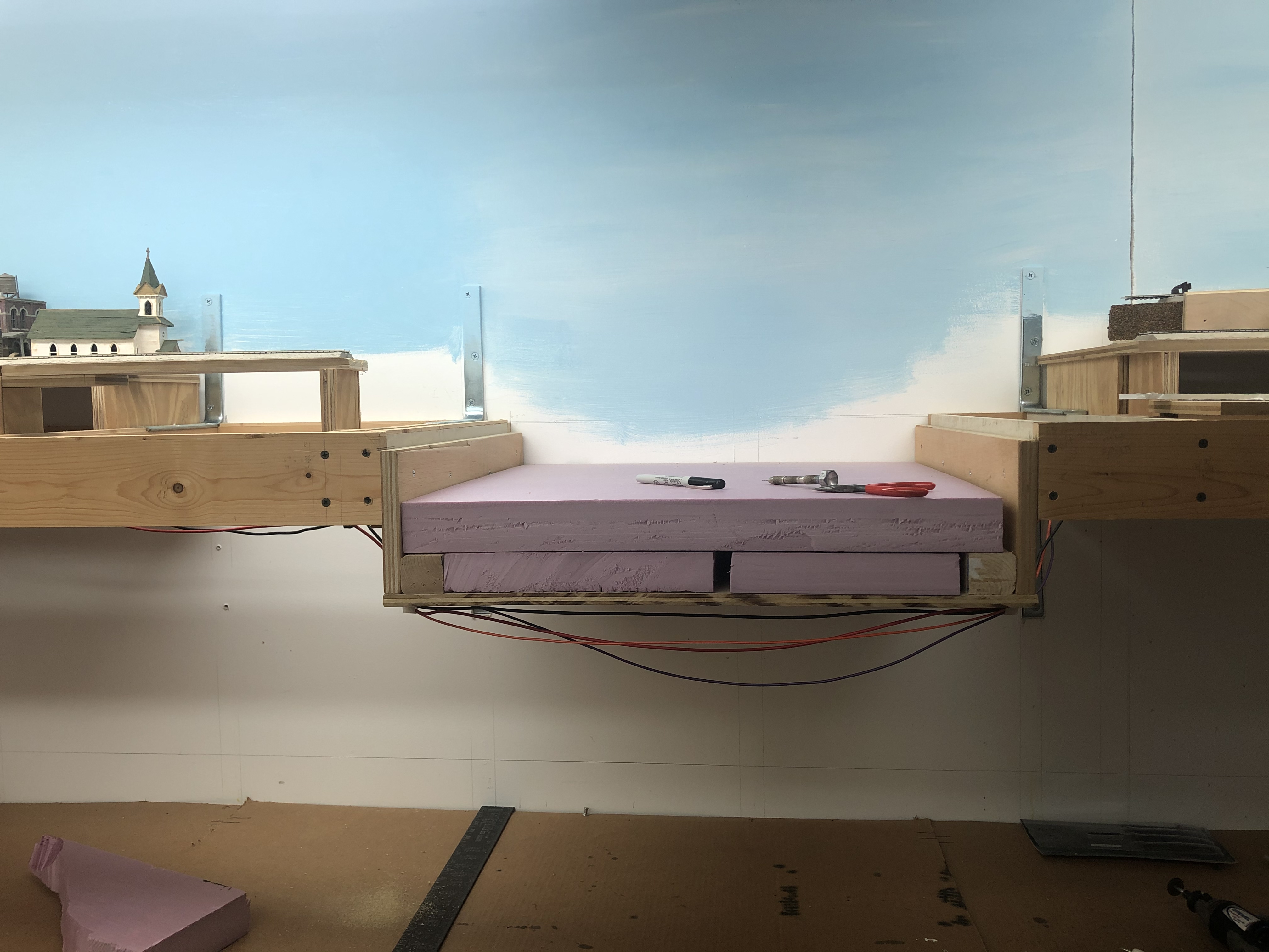
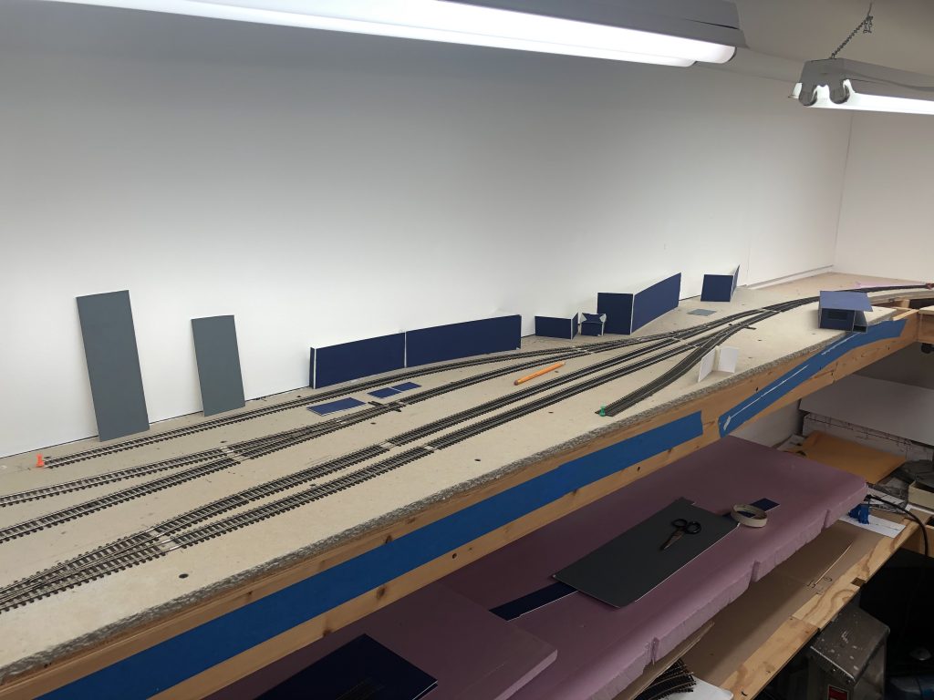
Coupled with the layout visitors, I have also been selling a lot of extra stuff on eBay. Over the last year or so I’ve really culled a lot of rolling stock and material from my collection. Much of it was sold at the GSMTS Timonium show, but much of it has been sold via eBay. As I clean and dig through my things, I find more and more to list for sale which really helps motivate me to continue to refine my focus and standards for the layout. Also, the sales help pay for the layout materials and new freight cars that I come across. Here’s a photo of the layout from a month or so ago:
JMRI progress has been a real roller coaster. Yesterday morning, in a fit of frustration, I was ready to swear off the program (both literally and figuratively) after running up against a string of constant, baffling errors. Kelly talked me off the ledge and offered to help rebuild and refine my layout concept in the software. I’ve realized that JMRI is going to be the best solution for what I want to do with the operations scheme on my layout; it offers pretty much all that I want, even though I have a long way to go before I get to my goal. I do have a document which outlines all of my “givens & druthers” as well as rules, specs and other details about my scheme. This will be published later for anyone who’s interested. Also, if anyone wants to talk Operations or JMRI, please reach out! I’m neck-deep.
A byproduct of the layout visitors and the JMRI work I’ve been doing was that I put together manifests for four trains that I refer to as the “Bethesda Turn”, since Bethesda is as far as the track currently goes on my layout. After the visit, I ran these four trains as I intend to run most of my trains, and it was fantastic. Yeah, not all the switch machines are in place, and some of the frogs aren’t wired, but the overall feeling of what it will be like to operate the layout was there, and it was really cool. A taste of things to come.
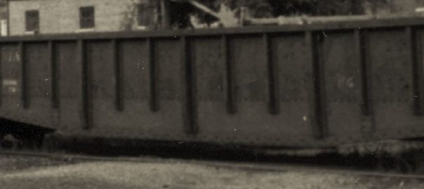
I find that in this hobby it’s important to have active projects in different areas of the hobby to keep things interesting. Last month when I got tired of installing DCC decoders and building trestle bents I switched over to building a freight car kit. The one I chose from my shelf-o-unbuilt-kits was an old Intermountain PS-1 50′ Double Door Box Car lettered for Southern Pacific #650159, kit #40607-10, with a 1955 build date; just inside my era. I found this kit on the shelf at the Annapolis area LHS, Star Hobby, for a had-to-have-it price of $10. Side note: I-M seems to be taking reservations for a re-release of this kit right now!
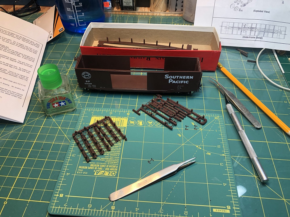
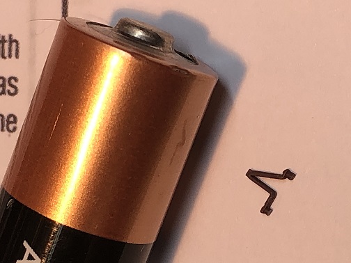
I hadn’t put together a challenging kit like this in many years and I had a blast. I upgraded it with a Kadee Apex running board, some Tichy end grabs and Tangent ASF A-3 wheel sets. (The prototype apparently had Symington-Gould A-3 trucks, but I haven’t found a manufacturer for those in HO.) The kit didn’t come with instructions, but thankfully I found some on the I-M website. It’s really nice they put the instruction manuals up on their site!
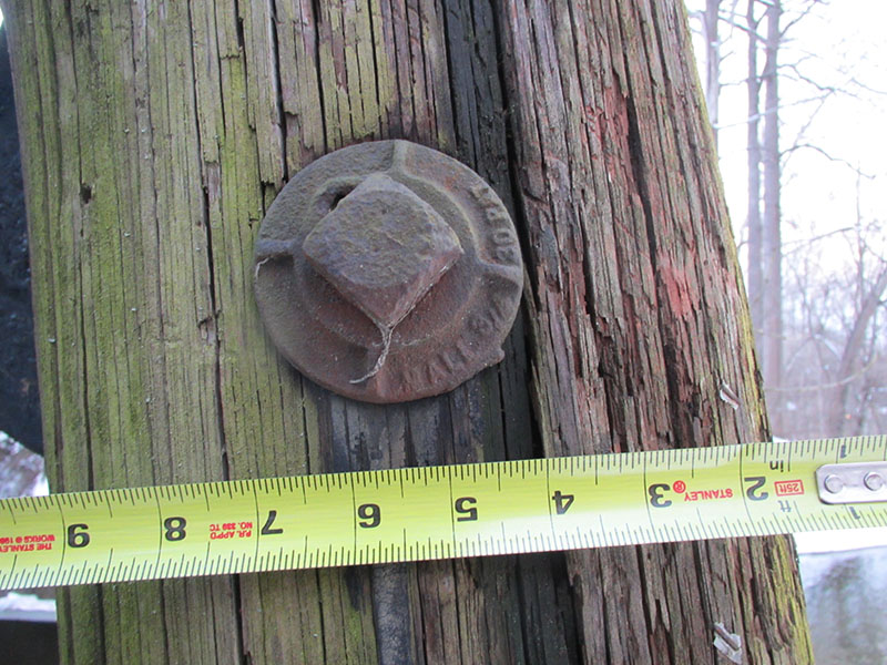
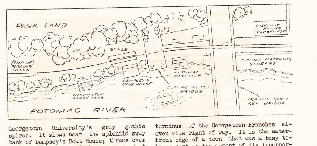
Car weights came in the form of wheel weights I collect off the ground at track day events, which I glued to the interior floor with Liquid Nails. The body was badly warped at the top and required careful attention to straighten when gluing to the roof. The doors were also ever-so-slightly warped but once in place looked fine. All in all, a neat car. I don’t have many 50′ cars so this one will look nice delivering lumber to Galliher Lumber in Georgetown.
Lastly, a word about the NMRA Achievement Program (AP). Over the winter I was inspired to begin participation in the various AP areas. A few of the folks in my club are diving in and working toward their MMR so I figured I’d join the journey. So far, not a whole lot of movement on my end. I’ve started organizing and reading through the materials but that’s about it for now. I just haven’t been making this a priority, as I’ve had other things going on requiring attention. However, I have been taking photos of some of my projects in preparation for writing up articles. I will definitely post links here once that materializes. For now, I’ll keep planning and aligning my modeling efforts with the various AP certification qualifications. I think of it like merit badges for adult model railroaders. I’m enjoying the challenge!
Like I said, this is just a quick, off the top of my head update. I am hoping to be able to post more, but with work being so busy and other things vying for my time, I do what I can when I can. Be well and keep in touch!


