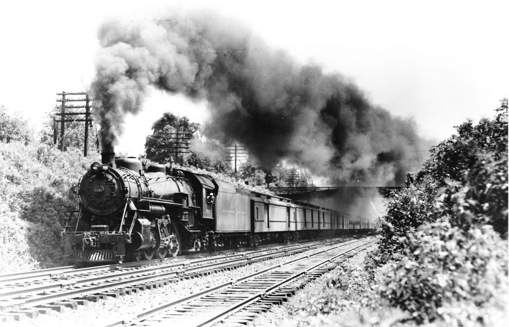
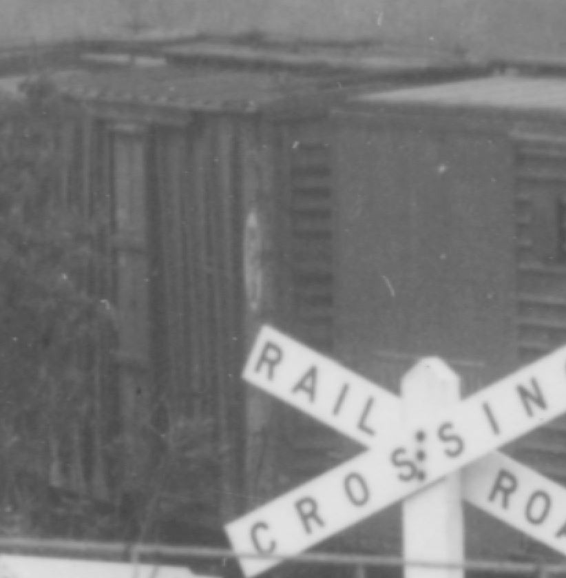
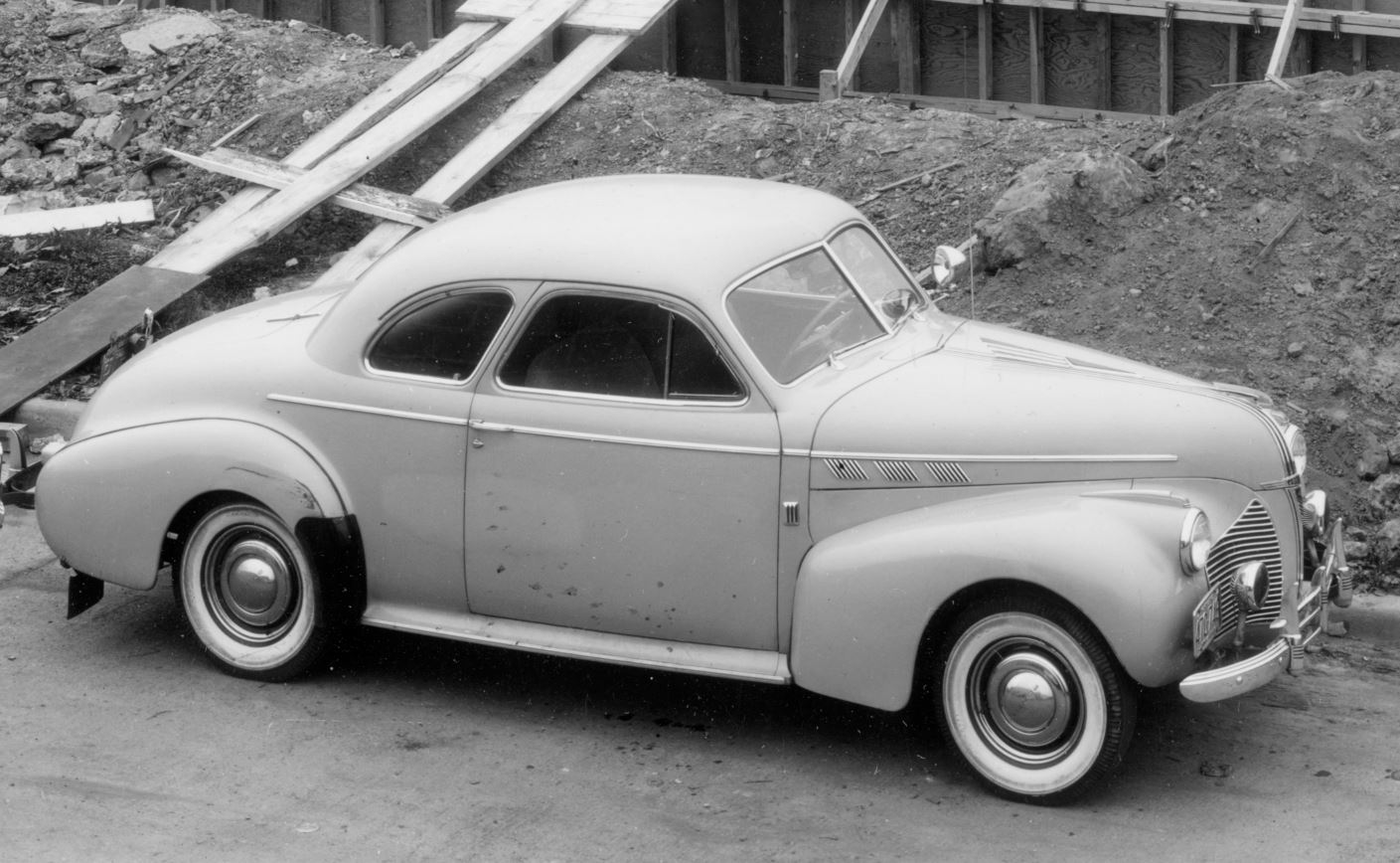
B&O Train no. 9, “NY – Chicago Express”, P-1d 5038, Georgetown Junction, MD, 1:22pm 7-29-43, Bruce Fales
I picked up this print off of eBay last week and was pleased at my purchase. I try my best to scoop up any Georgetown Branch-related photos whenever possible, as they are relatively rare and help me with my research. Even somewhat plain photos like this are helpful, as they show track arrangement, landscape, structures, such as the Talbot Ave. bridge seen in the background. It might seem small, but here I have a nice view of the railings, which I hadn’t seen before. Or had I…
Once I scanned this photo, and looked closely at the caption, a bell began to ring in the back of my mind. I realized that maybe I’d seen this image before. Maybe it wasn’t so long ago. And I was right. Three years ago, to be exact. I even posted about it to this blog:
It seems I purchased a negative of this very photo. Now, here’s where it gets weird. The negative I purchased is in rough shape. It’s a medium format and has tons of scratches. Is it a dupe? Is it a proof of some kind? Note the dust and scratches in the negative, and compare that to the print I picked up this week! Night and day. Is the negative I have an original that was just used and abused? It’s hard for me to say, but it’s an interesting story. I don’t regret buying the new print but I may have been more hesitant. Thankfully, it wasn’t too expensive and I can add it to my collection as a “better” print copy of the Fales (?) negative I already have.
In this view, we get a shot of the new bridge spanning Rock Creek where the long, high B&O trestle once stood. I imagine the worker is standing on the forms for the Capital Crescent Trail pedestrian bridge which will parallel the Purple Line. The bridge is significantly lower than the original B&O trestle, as they have lowered the grade here enough to allow the tracks to pass beneath the nearby Jones Mill Rd.
One of the challenges as a prototype modeler is deciphering what commodities traveled on the railroad that I model and from where they came or were going to. So far, my only clues are the venerable B&O Form 6 (a document which outlines sidings and businesses that they served, yet is not complete considering there were team track yards, shared trackage, etc.), photographs and some maps & diagrams which offer up clues. There are documents buried in various archives waiting to be uncovered but that’s another story. For now, I run with what I have.
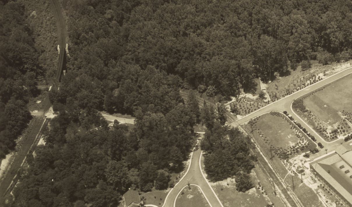
An excellent HABS/HAER document from the Library of Congress outlines the history quite nicely. Dalecarlia existed as a reservoir beginning in the mid 1850s, which received water from the Washington Aqueduct. The water treatment plant was built ca 1922 to help meet the growing population. DC began adding chlorine to its drinking water in 1923 and the Dalecarlia rapid sand filter came online around 1927 and used sand and aluminum sulfate to clarify the water. In 1928 the chemical building/head house was constructed, including a five-story tower which stored additional chemicals; alum, bauxite, lime and more. Likely, the B&O’s relatively new branch line provided a conduit for construction materials and consumables/chemicals for the construction and initial operations there. (Kelly and I uncovered what I believe to be an old siding where there was some sort of unloading device or construction facility astride one of the ponds, in the very northwestern tip of the facility.) Early photos indicate that the B&O had merely a short siding there for many years.
Dalecarlia Reservoir in 1930. The Georgetown Branch snakes along the lower, middle area of the photo, from top left to right. Note there are no unloading facilities present. Image from National Archives.1931 aerial photo. The GB tracks are seen on the left, filtration plant to the right. Note the siding, which appears to have fresh ballast and is perhaps new. The only access to this siding is the road seen passing from left to right. There is a small dirt track branching off and heading toward the siding. Perhaps for offloading supplies.
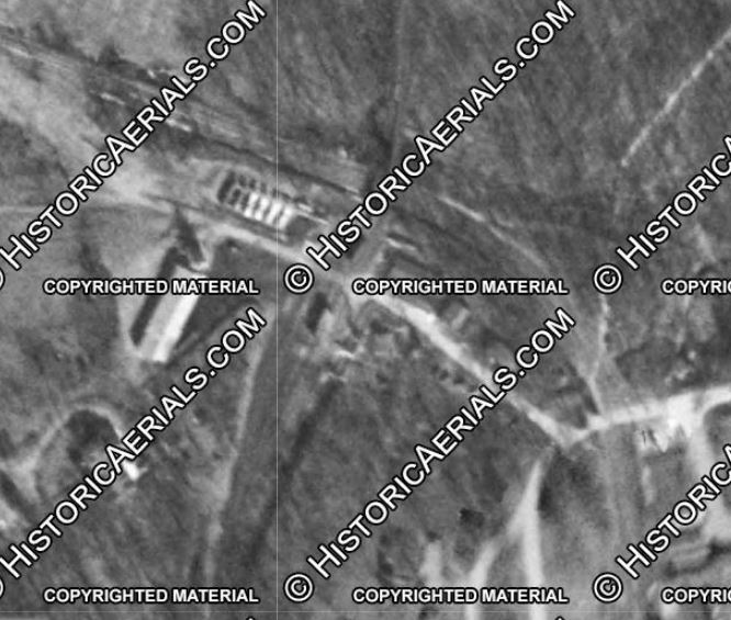
At some point, the B&O built a yard and an unloading system In a photo from 1947, I can see the unloading tanks which is the earliest photographic representation I have. An aerial photo from Historic Aerials shows the facility in 1949.
Visible in this 1949 aerial image is the small yard consisting of five tracks, including the main. I believe the left-most tracks were used for chemicals and the right tracks were used for sand and aggregates. Storage tanks are lined up to the north, across the access road. Likely there were various pump houses and maintenance structures nearby.
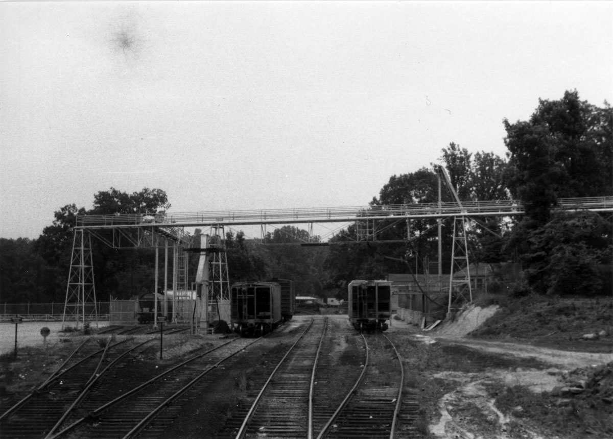
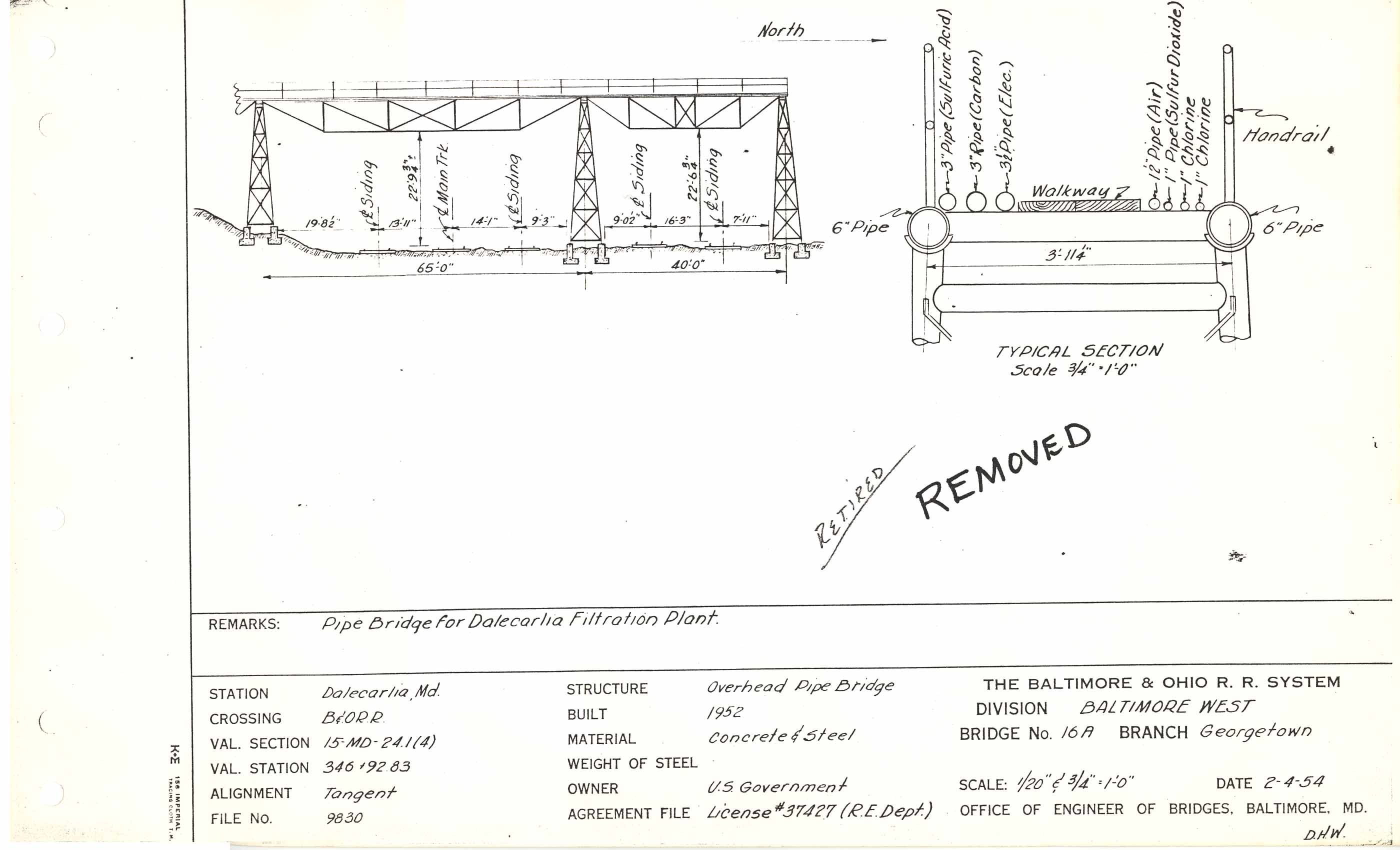
In a photo from 1956 shot by Ray Mumford, we get the best view I have of the yard and facilities. Note the overhead pipe bridge.
Dalecarlia Reservoir, May 30 1956. Photo by Ray Mumford.
Thankfully, the B&O documented the construction of this overhead bridge:
B&O Bridge Sketch Book
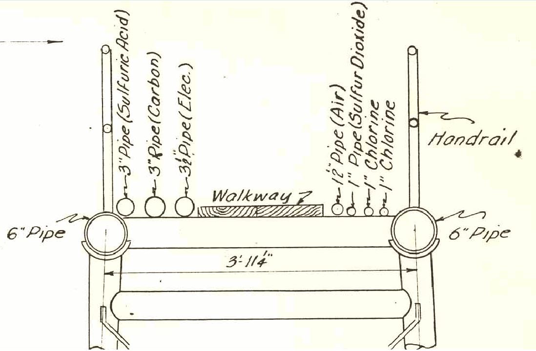
The plan indicates that this bridge was constructed in 1952, perhaps replacing or upgrading an earlier structure; I have no photos to determine this, yet. Here is a detail of the pipe bridge cross-section:
Detail cross-section of B&O chemical bridge at Dalecarlia.
So back to our original question about commodities. This cross-section has labels on the pipes, indicating what they were used for. Nice! We see: sulfuric acid, carbon, “elec.” (electrical?), air (compressed?), sulfur dioxide and two chlorineconduits. Combined with the information found above – sand, aluminum sulfate, alum, bauxite, lime, etc. – we start to get an even better picture of what arrived at the water treatment plant via the B&O. This helps me to hone in on freight cars and operational schemes for my layout which is a crucial thought exercise for planning what cars I want to model and what purchases I want to make for my fleet.
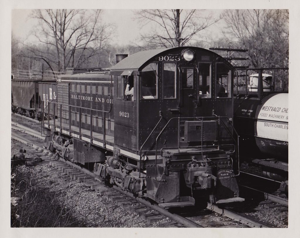
I still have so many unanswered questions – like what did the plant look like in the 1940s? What were the chemicals used for? What was stored where? How did the unloading facility work, exactly? What shippers sent cars to the reservoir and what rolling stock was used. Someone once mentioned seeing a “chlorine train” going down the branch with a few cars. Did the B&O have a dedicated train for chlorine on the Georgetown Branch? This offers an interesting operational possibility, if true. These fine details are what run through my head as I compile this information and seek answers and solutions. For now, I’ll have to go with what I have. We’ll probably go in a bit deeper later on some other speculation and theorycrafting, but until then, enjoy this photo of a train at Georgetown Junction that includes a chlorine car from Westvaco in WV:
December 31, 1959. B&O 9023, an Alco S2, is coming off the Georgetown Branch, tying up the Metropolitan Br. mains at Georgetown Junction. Visible to the right of the engine is an interesting chlorine car. Markings read “WESTVACO CHL[ORINE], FOOD MACHINERY & …, SOUTH CHARLES [, WV], LEASED TO…, WESTVACO CH…, WATER CAPY OF TANK, 493?? LBS.” My collection, eBay purchase, photo by Bill Williams.
My copy of the 1954 ORER indicates 12 cars for Westvaco, with reporting marks WVCX. By 1959 I am sure they had more but I need to get my hands on an ORER for that year. Onward!
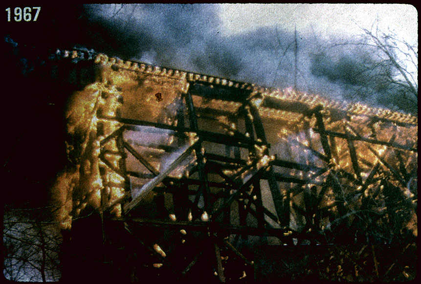
This post is sort of a mental dump from several months ago regarding a curiosity I discovered while doing research on the Rock Creek trestle for the model I’m constructing. Good photos of the trestle are very rare. Doubly so for older photos from the 1940s and earlier. The trestle was located in an area with a decent amount of vegetation and was a bit out of the way. I only have a few images of the trestle that date from the timeframe in the 1940s-1950s that I model, and they are mediocre shots at best. It was a difficult structure to photograph! But, they are like gold to me. They are all I have! They are the only visual representations of something that was very special and existed in various arrangements over time due to rebuilds, strengthening, vandalism/fire and flooding damages.
Ca. 1967. Photog unknown. Collection of W. Duvall. An arsonist’s fire gutted the trestle five years before Agnes would destroy half of it in the major flooding of Rock Creek. Note the diagonal supports on the outside of the trestle. So which side of the trestle was this photo taken from?! North or South?
Because there are no strikingly significant differences between the North and the South side of the trestle, I have always struggled to determine what I was actually looking at in the photos; North or South side? The small refuge bays that jutted out a few feet at the top were offset on each side in the same relative place, so if you stood on the ground below the trestle and snapped a photo, it would look nearly the same from either side. I had to find a way to figure out which side was which when looking at photos taken from the ground! But how?
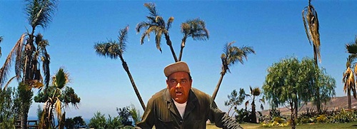
Anyone else remember this moment from It’s a Mad Mad Mad Mad Mad World? This was me moments before figuring out how to identify the North and South side of the trestle.
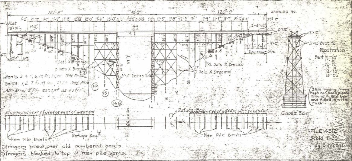
First let’s take a look at the bridge sketch. This view would be standing on the south side, facing north.
Bridge Sketch, B&ORRHS. Ca 1959, shows bridge after reinforcements were added.
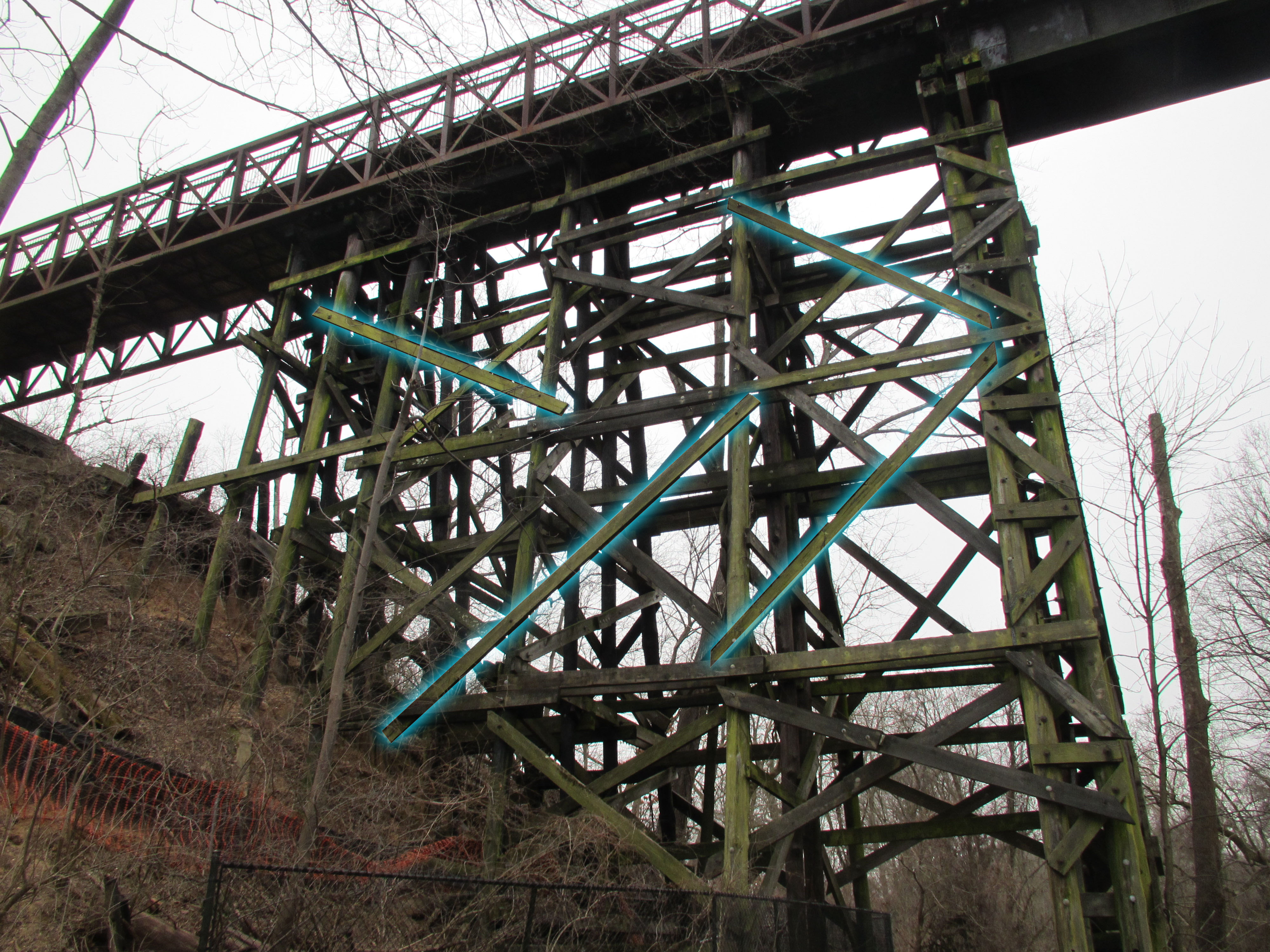
As I studied photos there was one thing that stood out to me. The large diagonal OUTER cross braces seemed to form an arrow that pointed toward the west. I first took a look at a few known photos that I shot of the East end of the trestle to see if there was something to this. Here is a view from the North side, facing South:
11/12/2019, North side, East end. Outer braces highlighted in blue.
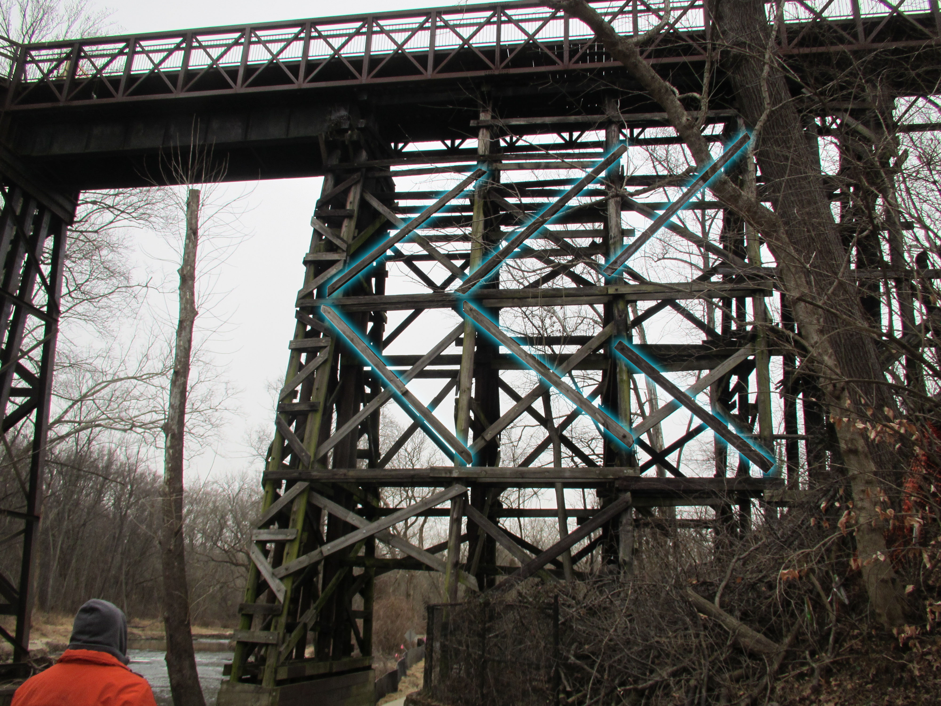
And here is a view on the South side, facing North, of the East end as well; the other side from the above image:
11/12/2019, South side, East end. Outer braces highlighted in blue.
And there it is. My “W” moment. The cross braces form “arrows” which always point West. Looking at some images in my collection which I previously could not determine the side confirmed my suspicion. Here is an image from ca 1946:
A view from below, ca 1946 or 1948. I have highlighted the outermost cross braces. I now know this shows the locomotive facing a westerly direction.
Note the side bracing, which I have highlighted in blue, pointing to the West! I have a few other images that I unfortunately don’t have permission to share here, which further confirm my suspicion. So, for anyone who is attempting to identify an old image of the Trestle, if you are curious which side you are looking at, just look for the outer bracing to “point” you the way. 🙂
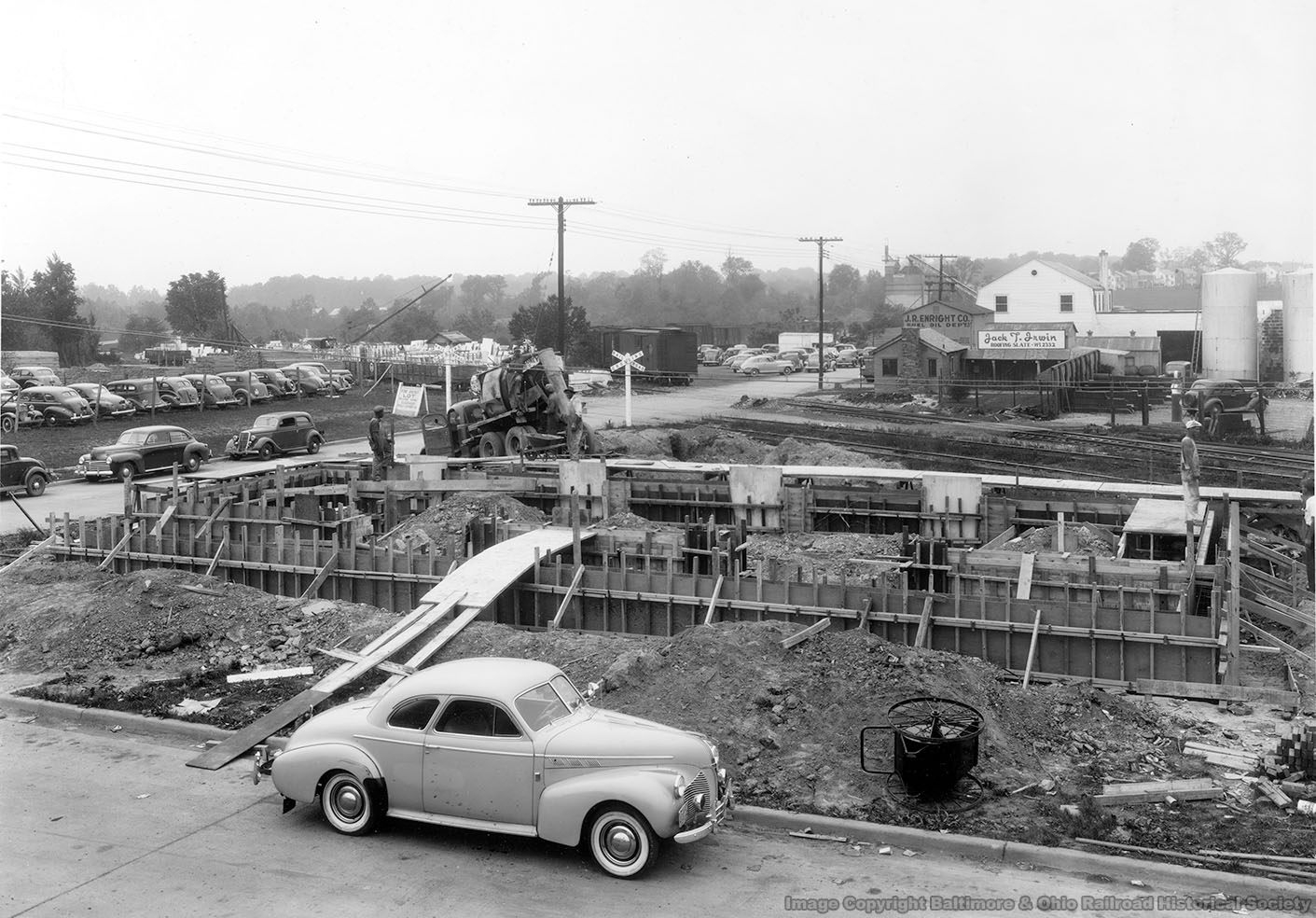
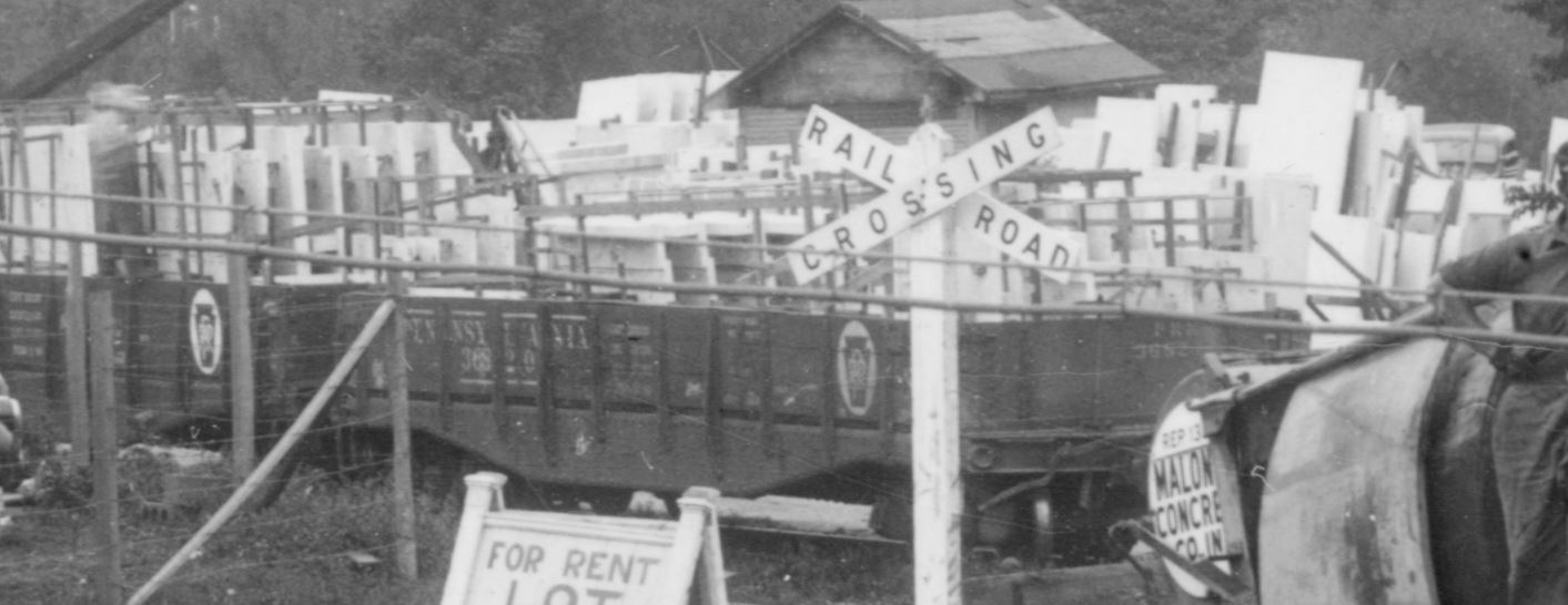
Well folks, this one’s a doozy. A friend, Brian R., who regularly volunteers at the B&ORRHS just sent me one heck of an image. You may recall a few months back he sent me a couple images of the Bethesda Freight House under construction. Well, here is one more that was shot weeks prior to the other one and shows a WHOLE LOT of the surrounding area. I get pretty excited when I get really nice photos of Georgetown Branch subjects, but this one is really very special and so chock-full of details, it’s hard to know where to begin. Let’s dig in. First, here is the full image:
Freight House Construction, Bethesda, MD, May, 1941. Photo courtesy B&ORR Historical Society. Depicts early construction of the freight house with footings being poured. Of note are surrounding yard and town area.
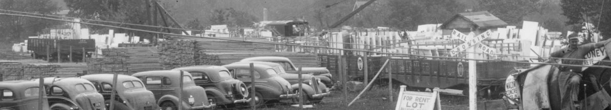
So there’s a lot in the image and what is funny to me is the construction of the freight house is not the primary interest. I picked out several things of interest. Let’s take a tour around the photo. First up is the yard area, largely visible behind the Maloney Concrete cement mixer. The yard is choc-a-block full of what appears to be marble or limestone. I have references to stone being delivered to Chevy Chase for the Washington National Cathedral and of course the extension of the line in Georgetown to serve construction of the Lincoln Memorial, but I have never heard of any stone deposited in Bethesda on a scale such as this! Have a closer look:
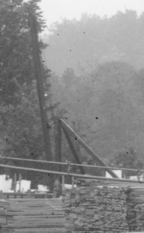
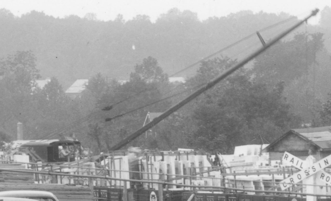
As far as the eye can see, stacks and racks and car loads of stone. Impressive! There are even two unloading devices; one, a stiff leg derrick visible to the left and a crane of some sort, likely an early Burro Type 15 or 20, similar to this one seen here.
Stiff leg derrick.Small crane. Note, the “smoke stack” seen to the left is actually from a building in the distance, not the crane. Note that the crane is facing almost perpendicular to the photographer. Also note the position of the operator in the open cab, with what appears to be the drum and hoist mechanism opening to his right. The crane is quite short in length, which steers me to think it’s an early Burro Type 15 or 20. Another image of the Type 20 patent design.
Getting a bit closer to the nearest gondola, I can see that it’s a PRR gon, and the number looks to me like 368270. A quick search in the 1943 ORER shows that this falls into the PRR GB class GRA, constructed around 1916 and modified from the GR class by adding 3′ to the overall length. These cars were somewhat plentiful in 1943 with 590 listed in the ORER. (By 1953 this number had dropped to only 31!) Thankfully, Westerfield offers a resin kit of this car, for anyone interested in modeling it.
PRR GB GRA class gondola, number 368270.
There are other GRA class gons in the yard, identifiable by the slightly stretched space between the middle braces.
Another PRR GRA gondola.
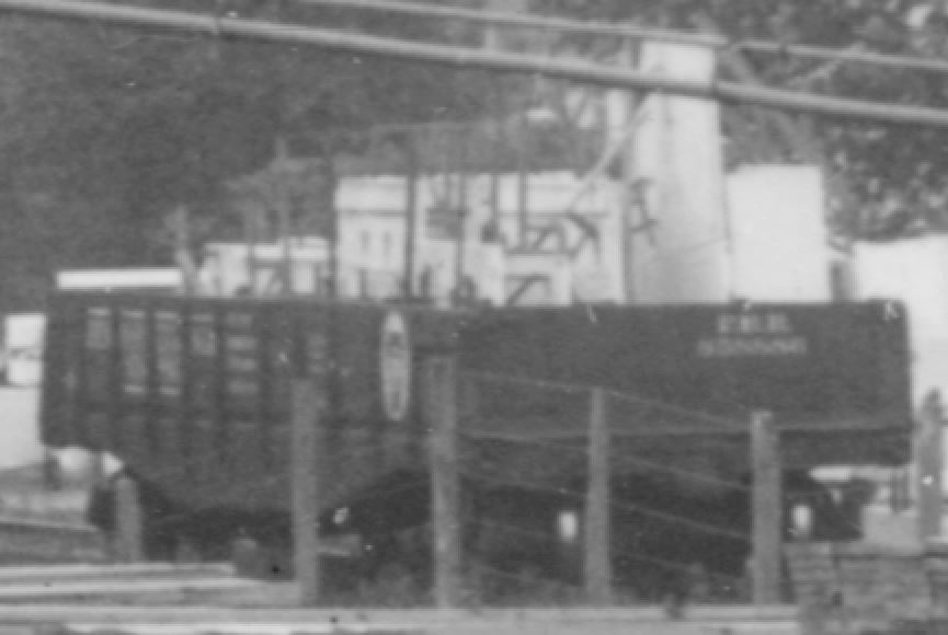
Let’s look at the other freight cars visible in the photo:
A long string of freight cars, all apparently boxcars, stretching on the siding toward Maloney Concrete.
The first one is obviously a PRR car and appears to me after some careful study to be numbered something close to 123951 – my confidence is medium, here. If this is accurate, and based on the overall design I think it is, this would be a class X28a boxcar, rebuilt from door-and-a-half X28 class cars in 1933 and of which there were 4957 listed in the ORER in 1943. (In 1953 there were still 3676 listed.) Some info here. Thankfully, Funaro & Camerlengo offers a resin kit of this car if you’d like to model it in HO. Decals here.
PRR X28a boxcar.
The next car appears to be another PRR car, but there’s much less to go on. My guess based on the panels and bracing is something similar to an X26 class boxcar, as they were plentiful; in 1943 the PRR had over 6000-some listed. Again, Funaro & Camerlengo offers a resin kit of this car as well as Westerfield.
Likely PRR class X26 boxcar.
The rest of the cars are so far away it’s very hard for me to discern. Perhaps some of the steam era freight car gurus can pick them out. 🙂 Next up, check out the lumber in the Einsinger lumber yard:
Einsinger Lumber; partially a parking lot.
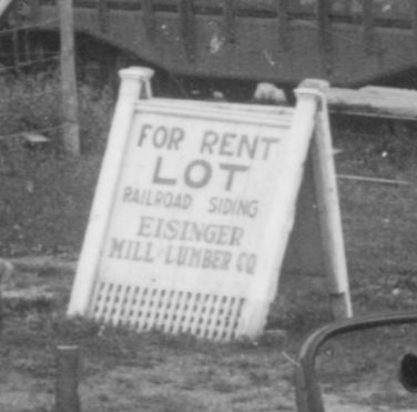
The siding is past those stacks of lumber. It’s interesting; at some point in the next few years, Einsinger would build more structures in this area to expand the lot. The cars occupy a space which would be the site of a long lumber shed. Photos from the late 40s and 50s will show the yard expansion. Oddly enough, in later years, the yard would once again be a parking lot and eventually a residential building. There was a curious sign off to the right, next to those cars:
Eisinger Lumber sign.
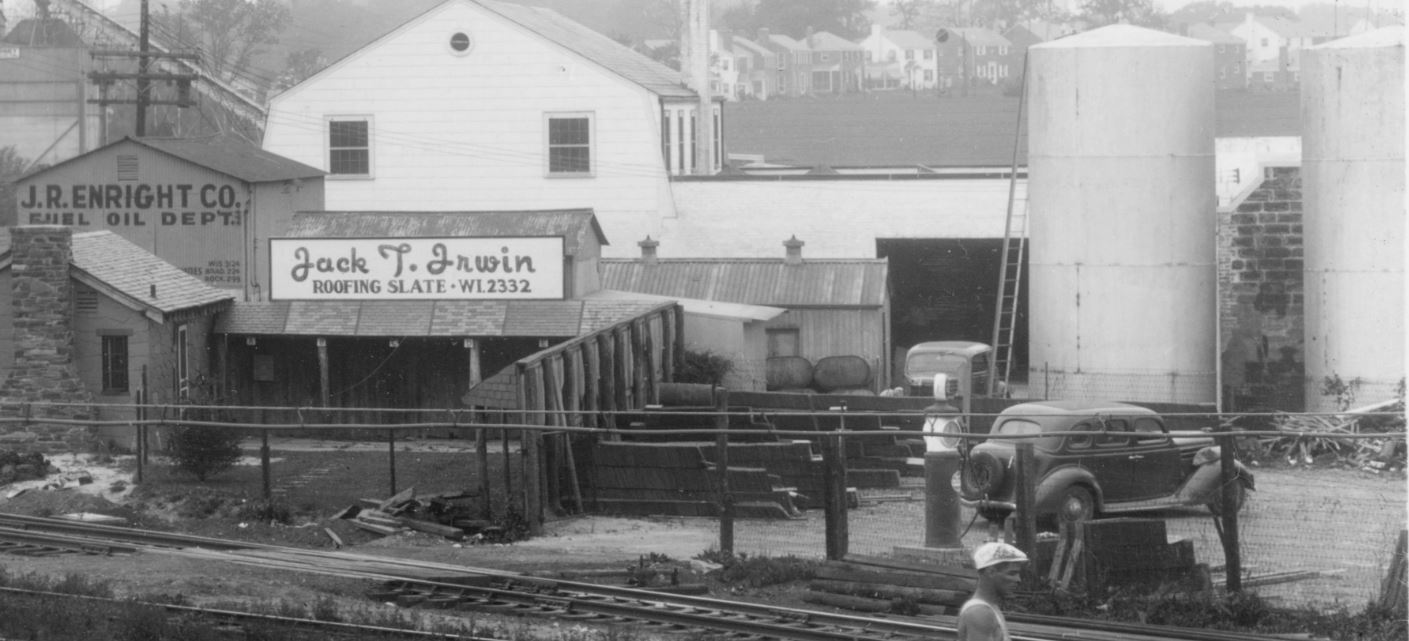
Would love to know the story behind that sign. Heading back over to the right is the Irwin Roofing shop. This is a particularly interesting spot, as it’s a showroom of sorts and there is SO much to see.
Looking closely, I see a well-maintained front lawn with a short walkway up to the small shop and a nice decorative sign hanging out front. The shop itself is adorned with stone all around. Coming out into the back yard, there is a small courtyard with an overhang, the roof of which features various types of slate roofing, each labeled with a letter; A, B, C and so on. A really neat detail! Irwin Stone is still in business today! Behind Irwin Roofing is Enright Oil:
Enright Oil.
Enright is interesting. I would imagine they unloaded from the second siding coming off the main, which would be just to the right of their plant. Unfortunately the photo cuts off there but we get some idea of their storage yard to the right. A couple storage tanks are visible as well as some bins (coal?) and a nifty gas pump which may or may not be in use there in the yard. Perhaps to fuel up their delivery trucks. I plan on modeling part of this on my layout. Obituary for J.R. Enright Jr. Also of interest here is the access to the yard with the small crossing over the yard tracks. In the distance is Maloney Concrete:
Maloney Concrete, barely visible in the distance.
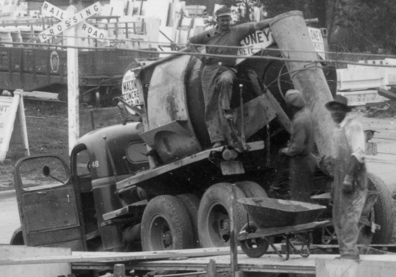
Speaking of Maloney Concrete, here is its mixer pouring ready-mix for the B&O freight station footers:
Maloney Concrete, truck no 48. If only someone would offer an HO scale model of this style mixer, I would be a happy camper!
And lastly, it’s hard to ignore all of those lovely late 30s – early 40s automobiles, but since I’m no expert, I’ll focus on just one. The up front and center 1940 Pontiac Torpedo Coupe:
Well, I hope you enjoyed the photo and the details herein. What are some of your favorite finds? What did I miss?! I have many questions such as what was all the stone for? What cranes were in the yard and during what years? How did Enright Oil receive their fuel? When did Eisinger Lumber expand and who were they renting the yard to? Also of note, the buildings along “Bethesda Row” had yet to be built. And to think, roughly seven months after this photo was taken, the USA would enter into WWII, further pushing the area to develop and grow. And yet, still no one has explained the greatest mystery of all; why did the Bethesda freight house never have rail service? The design is a curious one, with a garage for storage yet no rail service. That’s a discussion for another time.
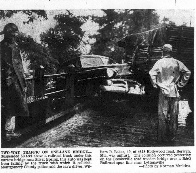
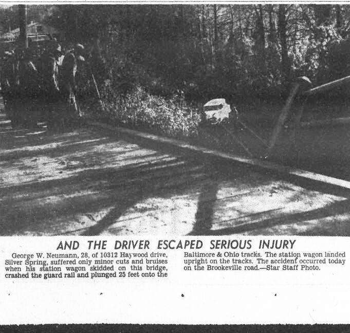
A member of the Friends of Forest Glen, Maryland Facebook Group recently posted a couple newspaper clippings from the Washington Evening Star which show two separate car wrecks that occurred at the Brookeville Road bridge crossing the Georgetown Branch. I suspect that slippery road conditions contributed to both. Pretty interesting!
Washington Evening Star, August 13, 1955Washington Evening Star, November 11, 1955
I knew that the old Linden Ln. overpass across the Metropolitan Branch just North of Georgetown Jct. was considered one of the most dangerous bridges in the country (!) at one time, but I did not know there were troubles with this smaller bridge just to the west. For reference, here is an image I scanned many years ago which was shot by W. Duvall, ca 1966:
Some will recall that the Purple Line folks intended to preserve and display the old girder(s) from the Talbot Ave bridge. They have just posted an artists rendering of what the old girders will look like at the Lyttonsville Station. Pretty neat. I’m just glad they were preserved!
Public artwork will enhance the #PurpleLineMD’s high-quality stations, aesthetic treatments and landscape designOne of…
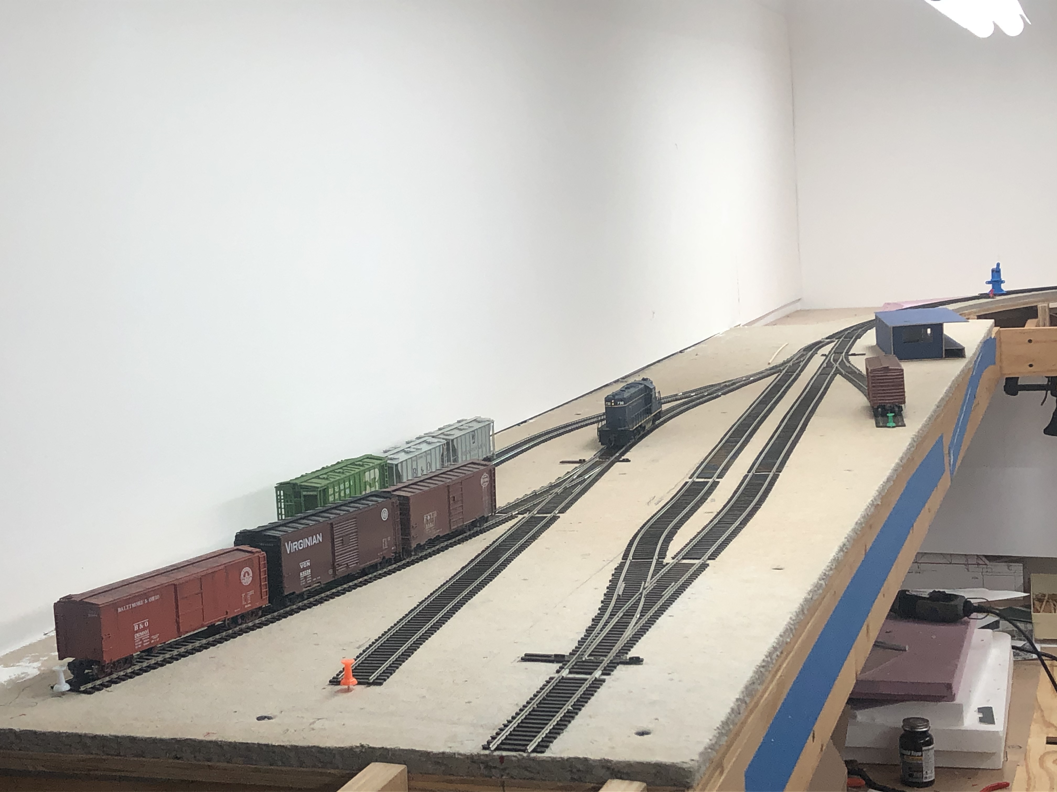
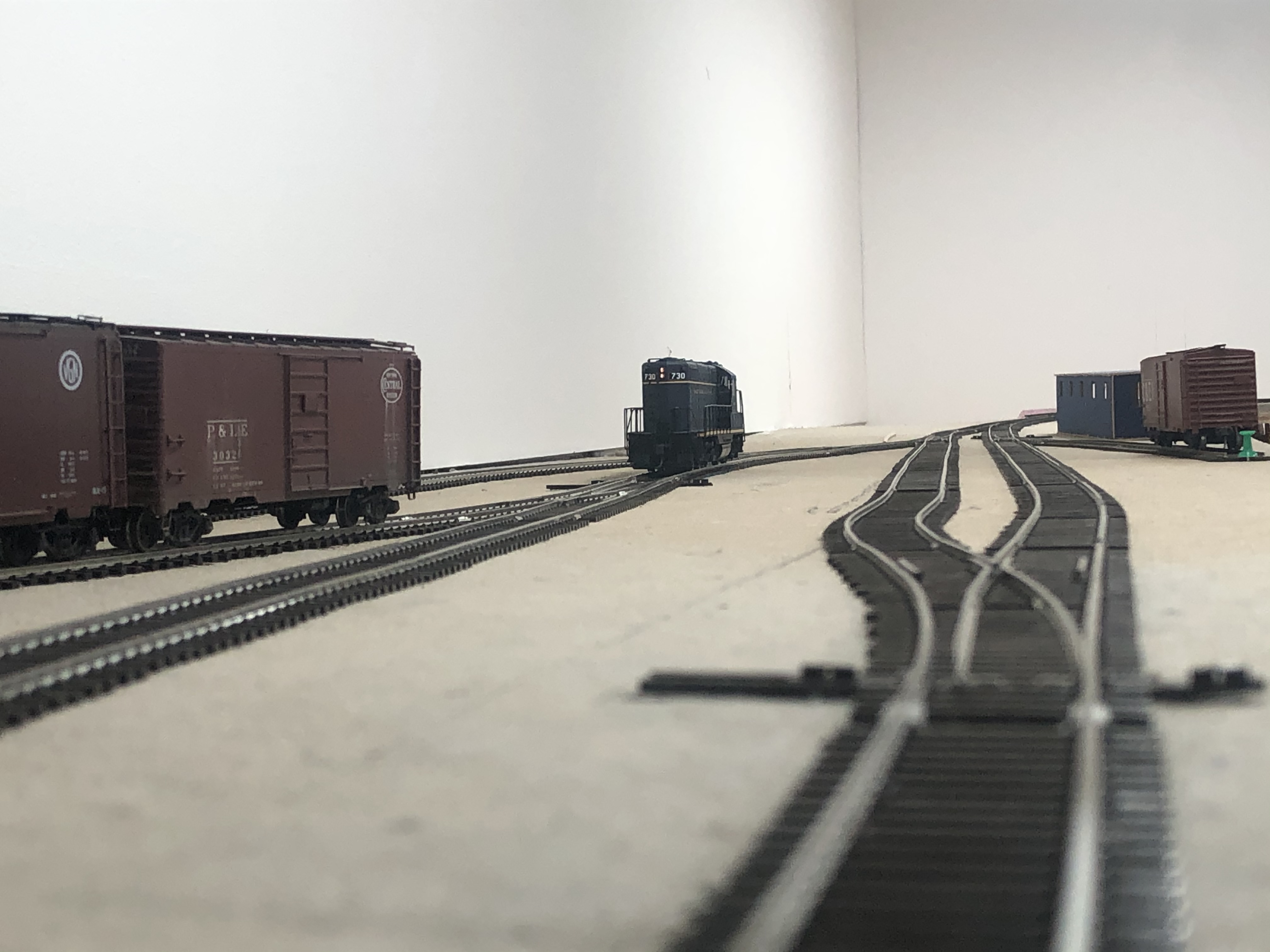
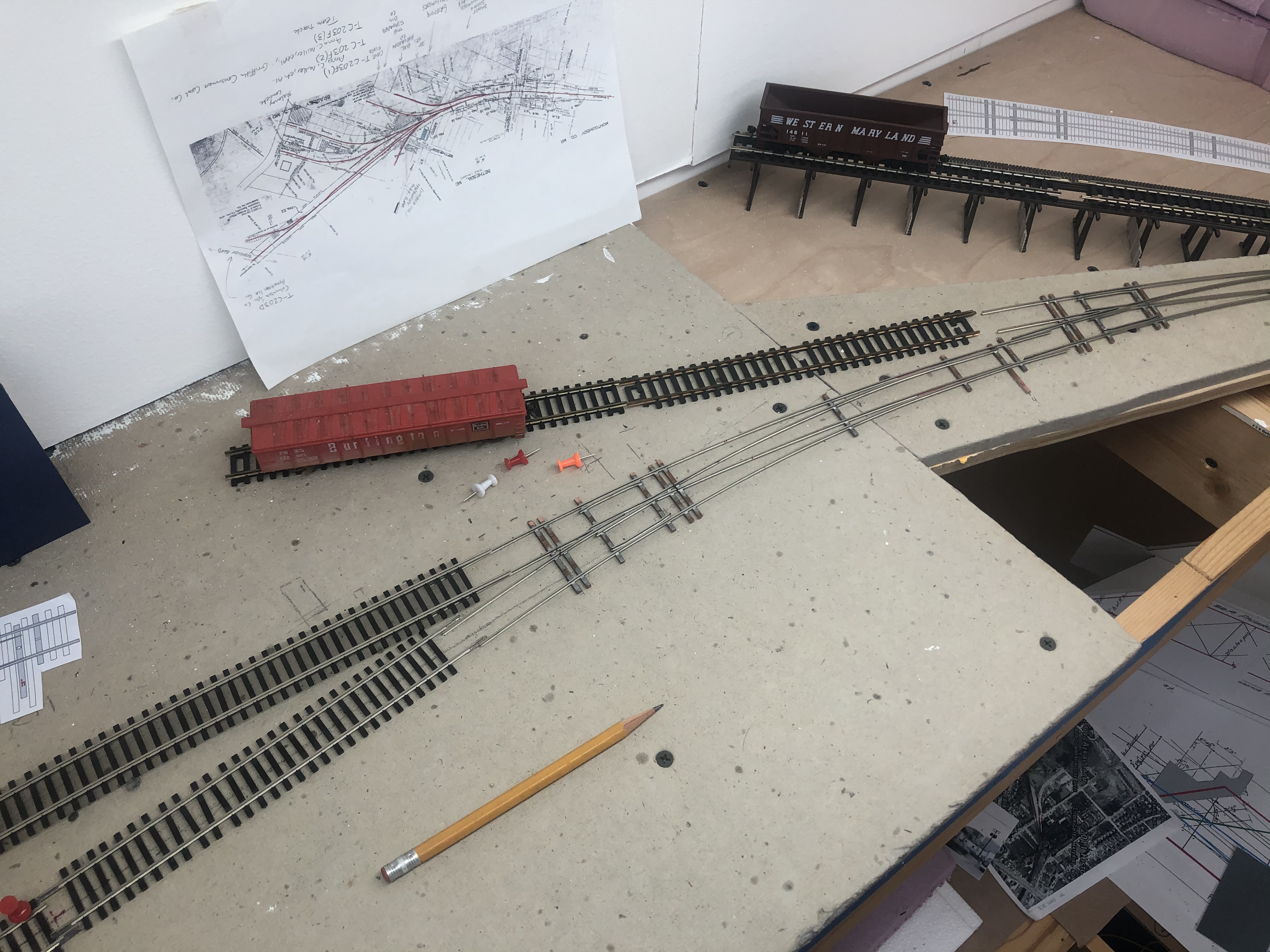
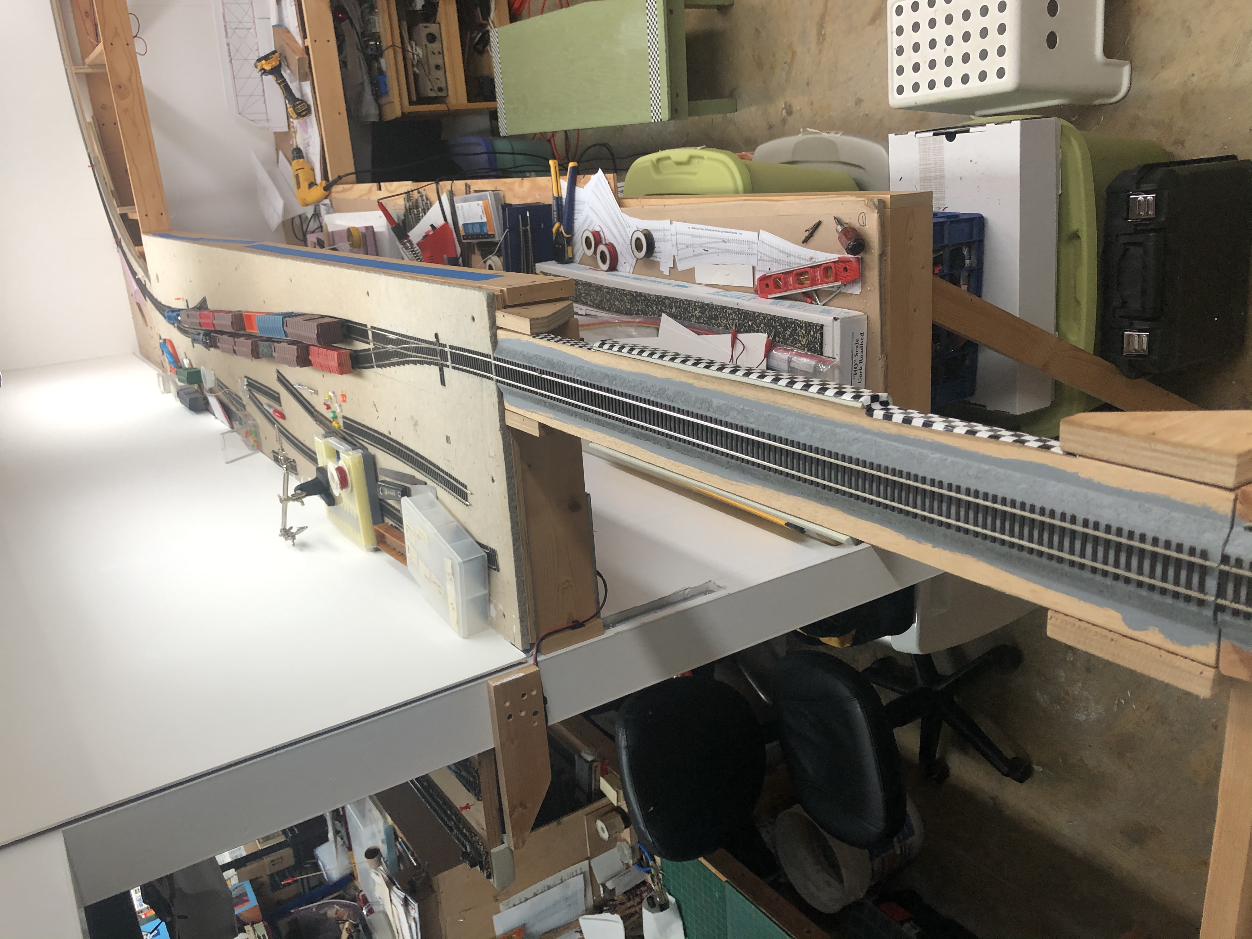
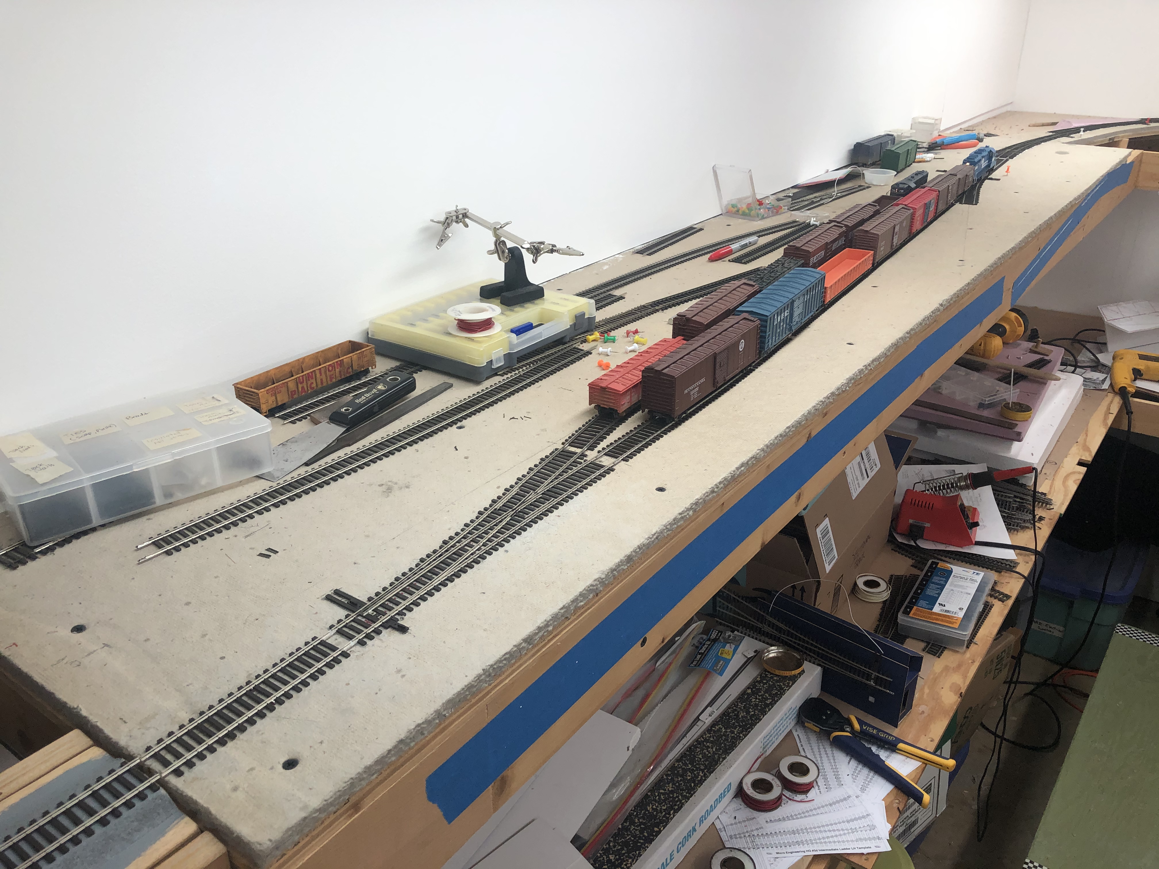
After another marathon weekend of working on the layout, I’ve made some great progress. Nearly all of the tracks in Bethesda are in. All of the drops are wired and nearly all of the turnouts have Blue Point manual switch machines installed. I cleaned off the table to get a look at the overall layout:
To orient you, the view is from the south end of Bethesda, looking Northeast. At the top are three turnouts with sidings going to Griffith Coal & Consumers, assorted warehouses, and the long passing siding. From the passing siding, the first turnout goes to Maloney Concrete & Frito-Lay. The second track which extends through the yard is the team track as well as a siding servicing Devlin lumber. On the right is a short siding serving Einsinger Mill & Lumber Co. A B&O track chart to assist. Note: some tracks don’t appear here, as they had been removed as they were taken out of service. You can see their “ghost” if you look closely, though!
I couldn’t resist doing a bit of operating. Man, this felt good!
Additional Projects
One thing that has really struck me is that over the span of eight years working on this project I have accumulated a lot of stuff to put this layout together. Much of it is piled beneath and around the layout itself. As I work, stuff gets shifted around. I’m at a point now where I have pushed myself out of my comfort zone to try new things. Some of these things include simple things like soldering feeders to the bottom of the rails instead of the sides up to more complex things like hand-building complex curved turnouts. I couldn’t do this without help and encouragement from friends and family who push me forward and answer all my stupid questions.
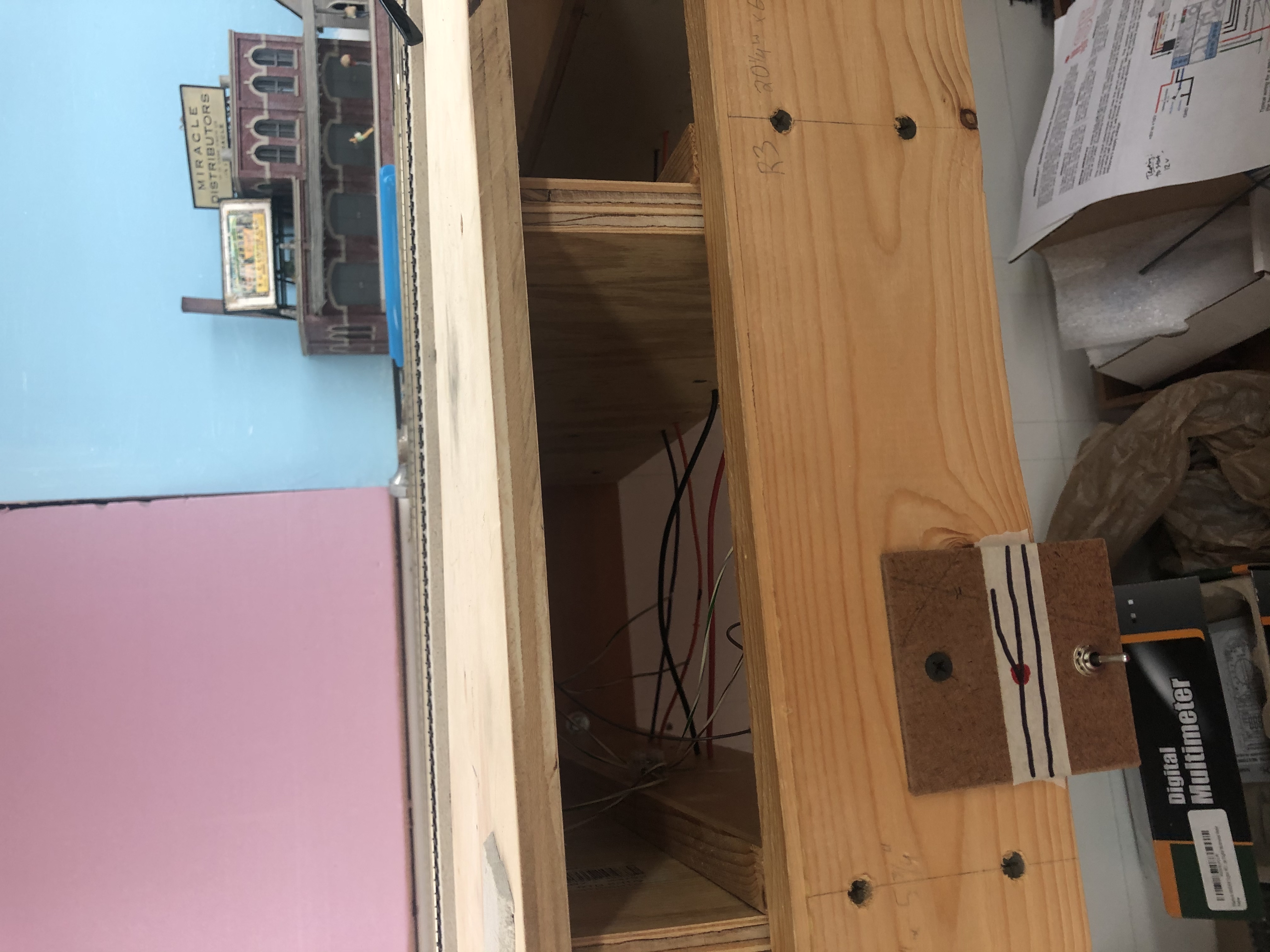
Lately I’ve been learning how to install turnout machines. I mentioned above that I used Blue Point switch machines in Bethesda. This decision was primarily based on the fact that I owned five already (that I had in a box of turnout stuff) and I realized a fascia would be nigh impossible with the way this section of the upper deck of my layout is built. There is no real room above or below it for toggle switches, I don’t want to cut big holes in the benchwork, and I don’t want to protrude out. Solution? Blue Point turnout machines. They use a push-pull rod/handle and can sit right on the fascia with minimal intrusion. Perfect. I’m quite happy with how they have been working for me. Bonus, I can wire the turnout frogs right to the machine.
Another project that has been in the hopper for a while are eight Iowa Scaled Engineering MRServo-1 units I purchased a couple years ago. (unfortunately, this product has been discontinued!) These nifty little things use a board that controls a micro servo mounted to a 3D printed chassis. Wiring up a DPDT switch and attaching to a power bus gives you a nifty little slow-mo turnout controller. They have a few different bases including a slim profile one to allow for remote installation in tight spaces. The MRServo units came in three types with additional features. This is the most basic of the three, featuring only turnout motor control. For now, it’s all I need. I plan on adding a Frog Juicer eventually to handle the frogs. These MRServo-1 units will be used on the upper deck from Chevy Chase all the way up to Georgetown Junction, as there is ample space below the track to install a fascia with toggle switches.
Power bus wires were run throughout the upper deck, both sides. I picked up a bag of inexpensive terminal blocks via eBay a few years ago and they are tremendously useful for projects like this. They can easily be trimmed to fit whatever size you need and held in place with a screw.I made a temporary fascia panel for the switch mount.
I am progressing my way through projects that have loomed over me for years. It feels great to burst through and make real progress on this layout and I’m learning so much along the way. I ran a train all the way from one end to the other with no issues whatsoever. Like so many things, when you break a project into smaller pieces it takes away some of the mystical difficulty, making it a bit more manageable. I have been crushing these small hurdles left and right. I am hoping to have a video in the next few weeks showing off the progress.
And then, once the upper deck is done… it’s on to the lower deck! Woah!! But first, I gotta do something about all that JUNK! (ha)
Pic from January but it looks virtually the same. The price of progress. Some day that will be Georgetown!
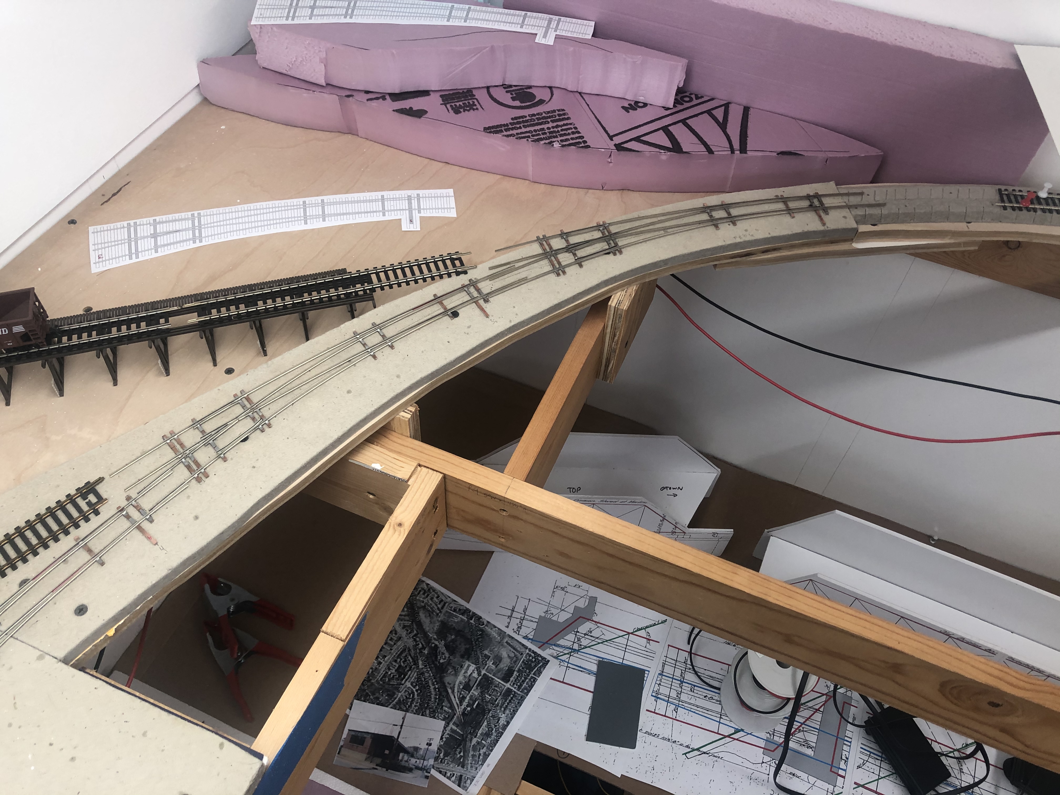
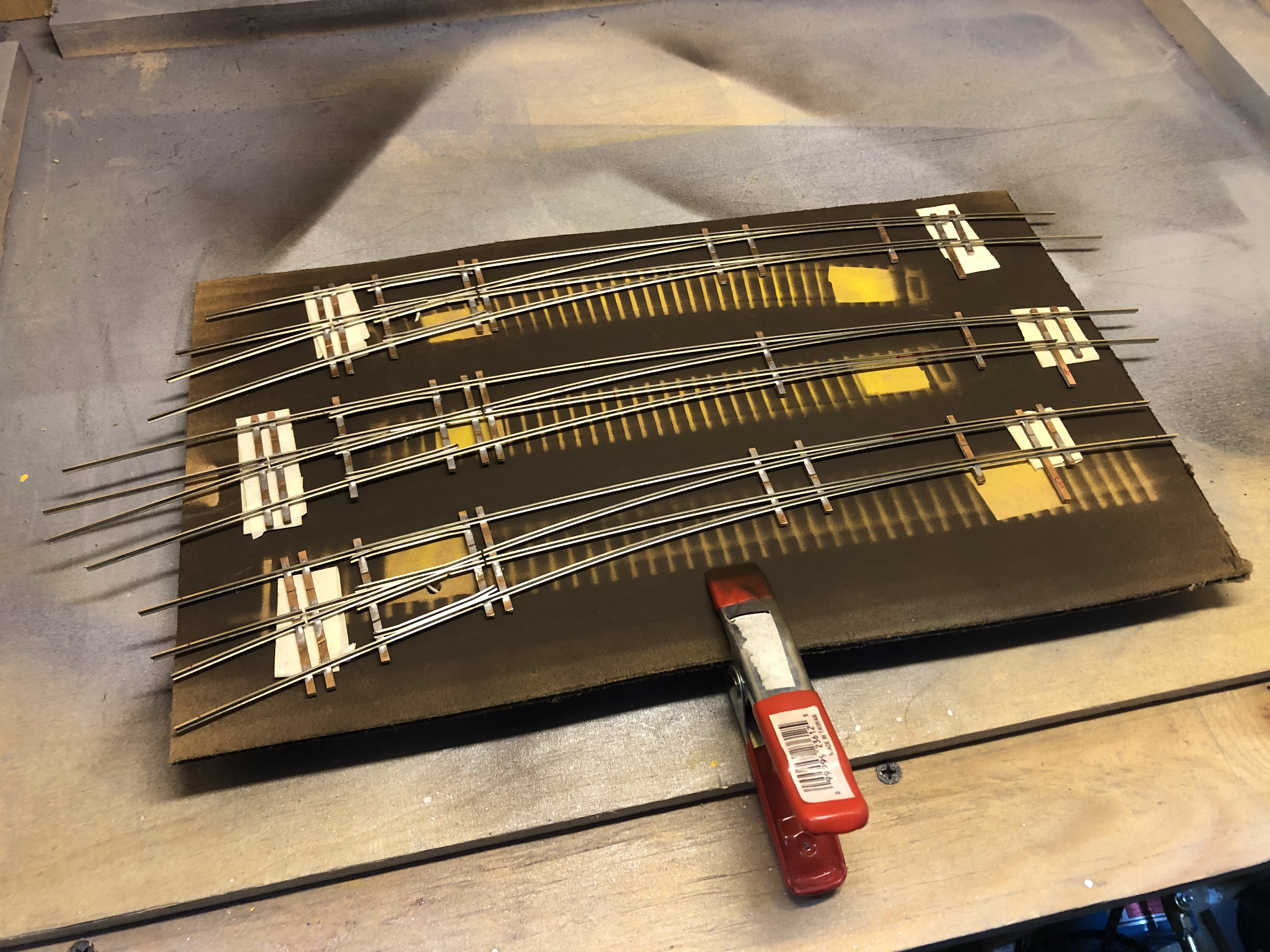
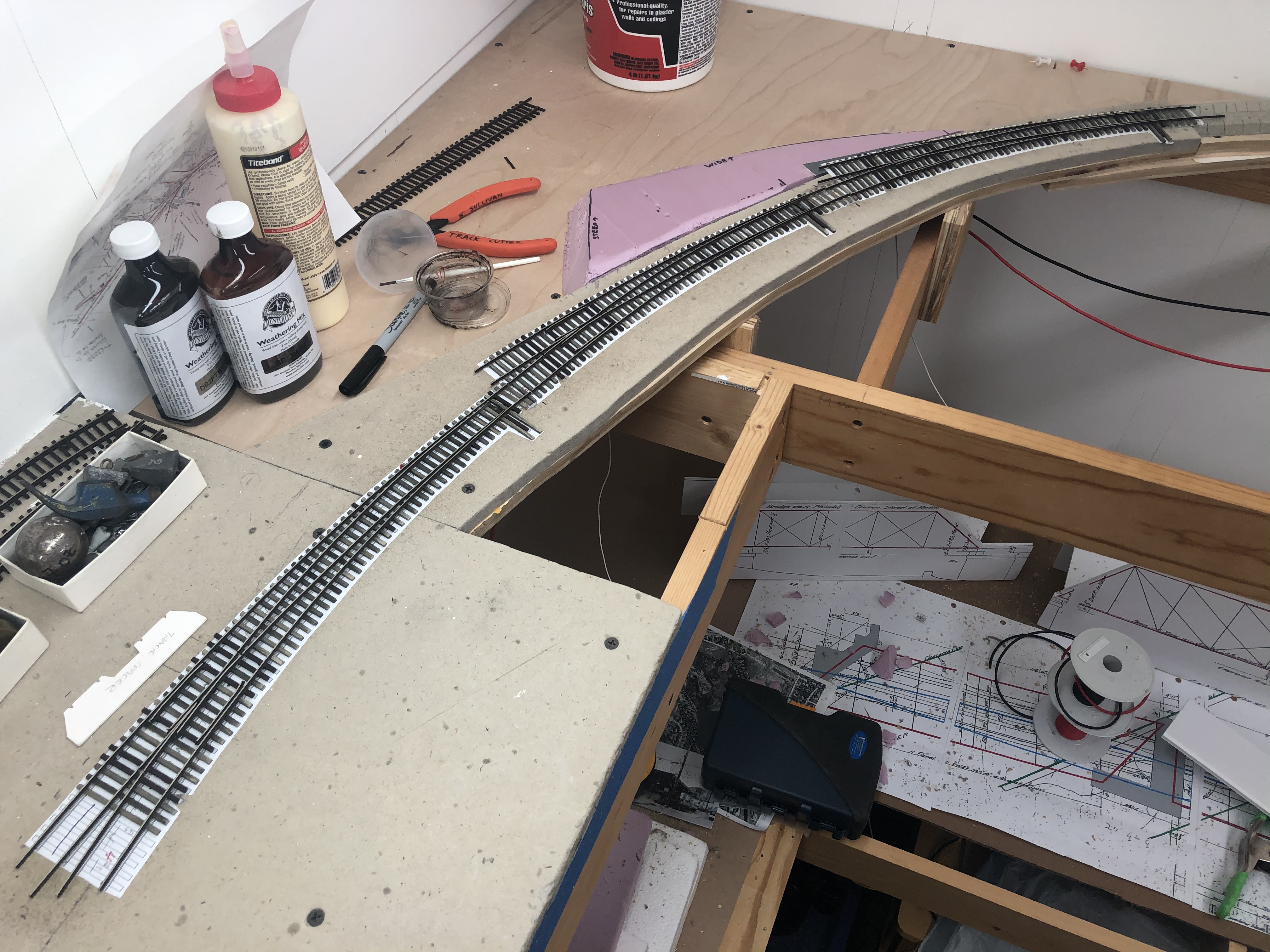
It has been a busy last week of working on the layout. Last weekend I spent much of the time getting the three curved turnouts that lead into Bethesda in place and working properly. This involved quite a bit of work; test fitting, cutting ties, staining them, painting the turnouts, installing tie templates, installing ties, sanding, laying in the turnouts, fitting them, cutting them to length, attaching feeders and drilling holes for them along with holes for the switch machines. Once in place, lots of sighting and adjusting was done with the tracks in Bethesda before spiking things down and testing some cars on the track. A bit of filing here and there and we are in business.
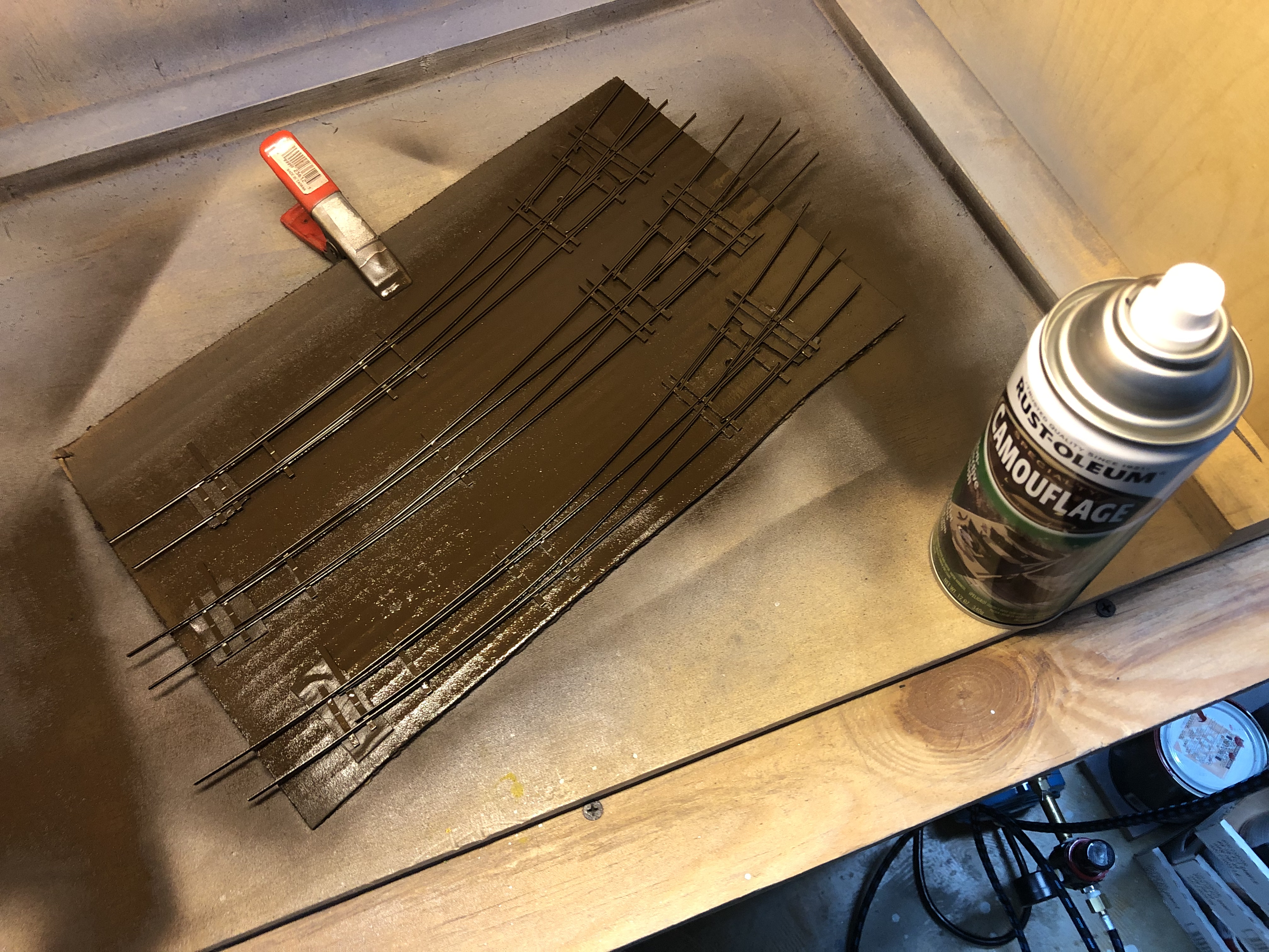
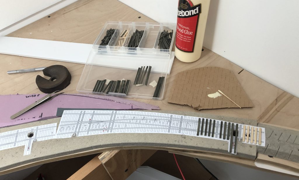
First step was to align the turnouts and mark their locations on the roadbed. I had to really tweak these to get them where I wanted. There is limited space, and having the turnouts end and begin in logical places to allow for operations was a challenge.More fitting. Tracks were laid loosely in place to get a feel for where sidings would lie.Preparing to paint the turnouts. Painted the turnouts with Rustoleum Camoflage Earth Brown paint. Overall, a nice effect. Beginning to install ties. Each bay in that box holds a set of ties for a turnout. I cut them all on the workbench using The Chopper, stained and dried them. I then laid them out in order (seen here) and installed with wood glue, one by one. Ties were weighted down as I went along.
The three turnouts are sized as follows from top to bottom: #8 50″ outside radius, 35″ inside radius, #8 60″/40″, and #10 60″/46″.
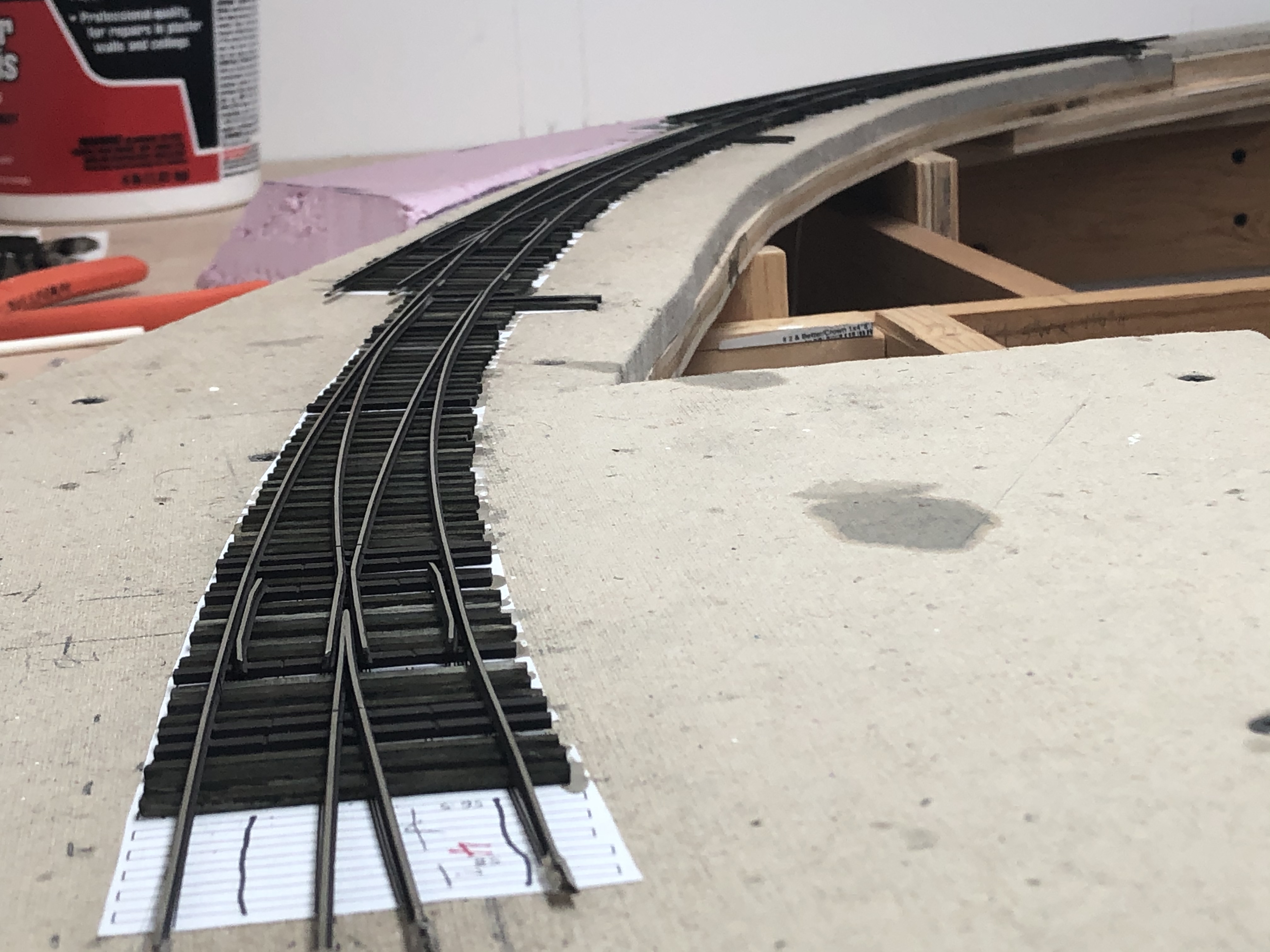
And here we are with all three turnouts finally laid in place. Rails have been trimmed and now I will fit the rail joiners and solder feeder wires where needed. Getting there!I just love the way these look. I left the last few long ties off because I wanted to see where I would need to join the adjacent tracks to the turnout and wasn’t sure if I would need to trim the rail back.
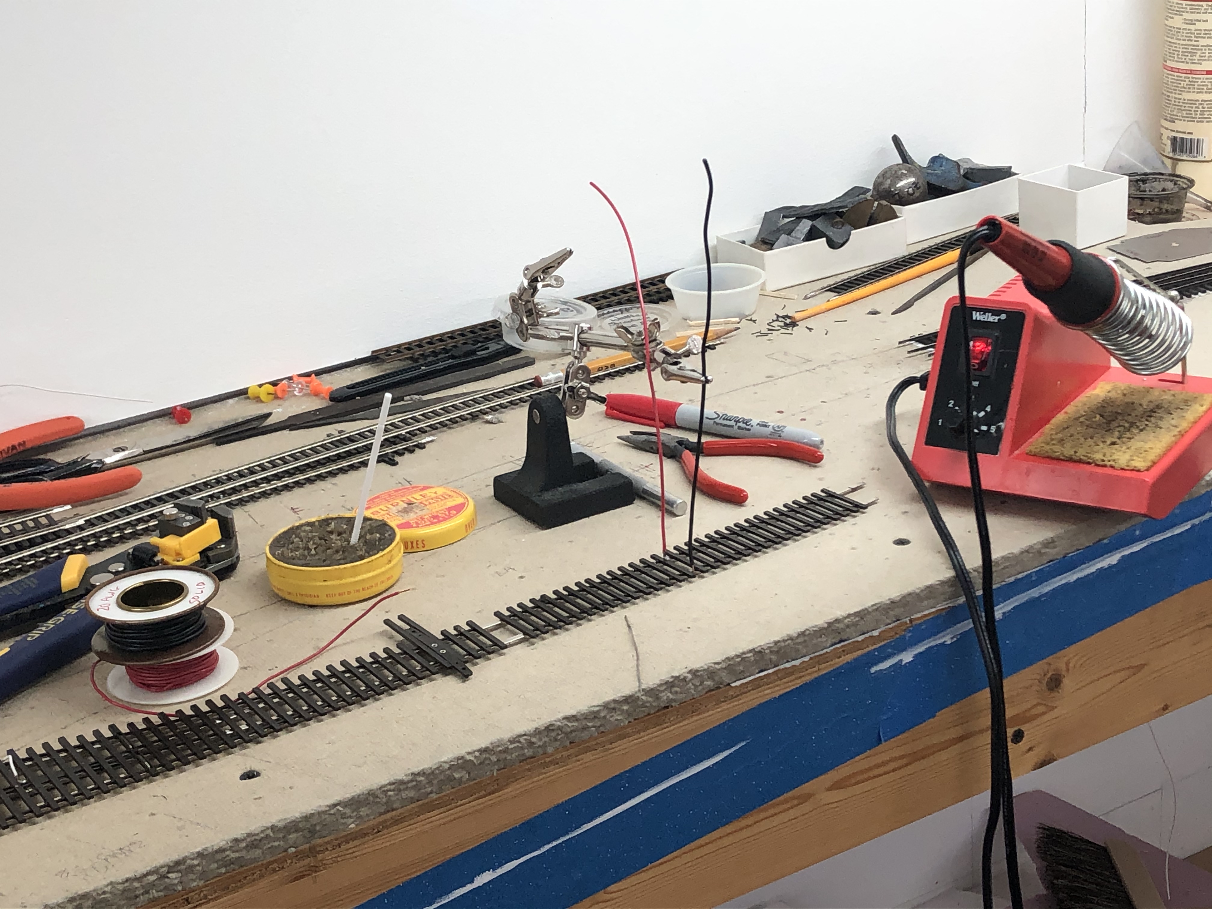
Soldering Feeder Wires
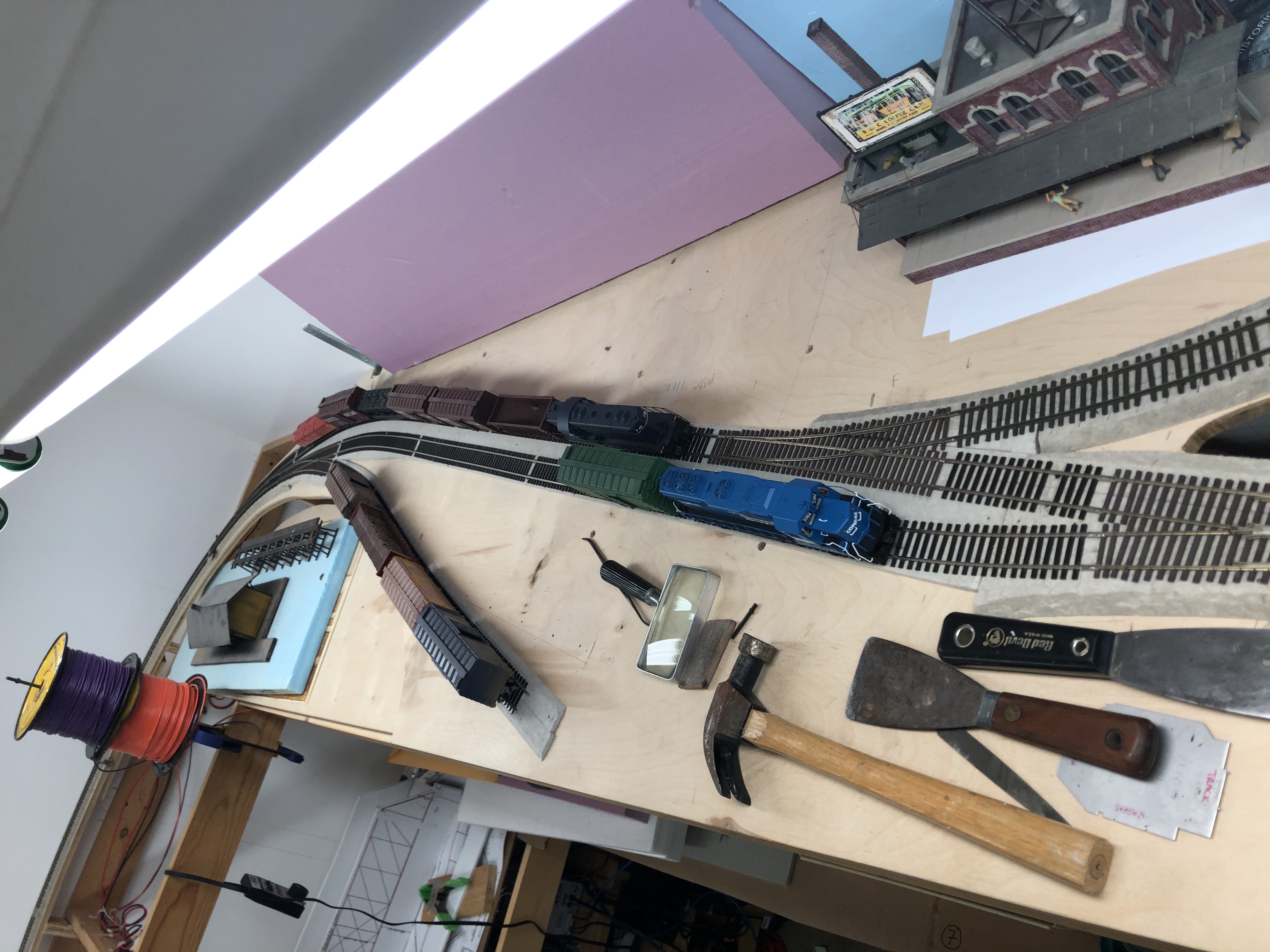
Some folks have asked me how I do feeder wires, so here is a quick illustration. A good friend, Matt R., convinced me to solder feeder wires to the bottom of the rails instead of the sides. This method leaves a clean look with no unsightly wires poking out, globbed onto the rails. It does take a bit of extra work, but once you get into a rhythm it goes fast. Here is my setup:
From right to left: My soldering station, a red Sharpie for marking drop locations on the rails and hole locations on the layout (for drlling), small needle-nose pliers, an X-Acto knife, “Helping Hands” vice for holding wires in place, flux, Irwin self-adjusting wire strippers and 22 AWG stranded or 20 AWG solid feeder wires. In the foreground is a small piece of solder.
I will typically mark the locations on the roadbed where I want the feeders to drop. This is done by marking each side of the rail and then the tops of the rail. Remove the piece of rail and drill a hole for each feeder. Flip the rail over. With the X-Acto, snip the small plastic spacers between the ties where you will solder the feeder. Strip about 1/8″ of insulation from the end of a feeder and bend it 90°. Using a micro-applicator, put a tiny bit of flux on the wire and the bottom of the rails. Straighten the wire and clip it in the helping-hands, positioning it so that the bare end is just barely pressed onto the rail. Now, using your soldering iron, place a tiny bit of solder onto the end of it. Then, press the iron and your solder into the joint and release after it flows onto the rail itself. This should only take a few seconds, most. You don’t want to melt the ties!
Once done, they should look like this. Ready for feeding through the roadbed.A close up. This is Walthers/Shinohara Code 83 rail. Also note, the feeder on top is stranded wire, and the feeder on the bottom is solid. Some days you just gotta run with what ya got!Here is what Bethesda looked like in the middle of this past week. The mainline was in place and the siding was tacked down.Trains in Bethesda. By Friday night here is the progress that has been made. The mainline and passing siding are complete. The lift-out bridge is operational. I installed a small spring switch on one end that kills power to the short length of track at the edge to prevent locos from creeping off the end if the bridge is not in place. It felt great to finally be able to bring a train around the bend into Bethesda! Hoping to complete the rest of the yard this weekend.One other project I took on was in Chevy Chase. The team track siding originally swung to parallel the mainline. This caused it to have a really sharp curve and I didn’t like the way it looked or caused trains to flow awkwardly. I widened the curve a bit and gave it a bit more room.


