I was unable to find anything Georgetown Branch related at this time, but I will be checking back and will update this post when I do. Could you find anything interesting on there? I hope so! The collection really is fantastic.
UPDATE: It’s Jan 14th, 2020 and I revisited the National Archives collection to see if there are any new images. I found two:
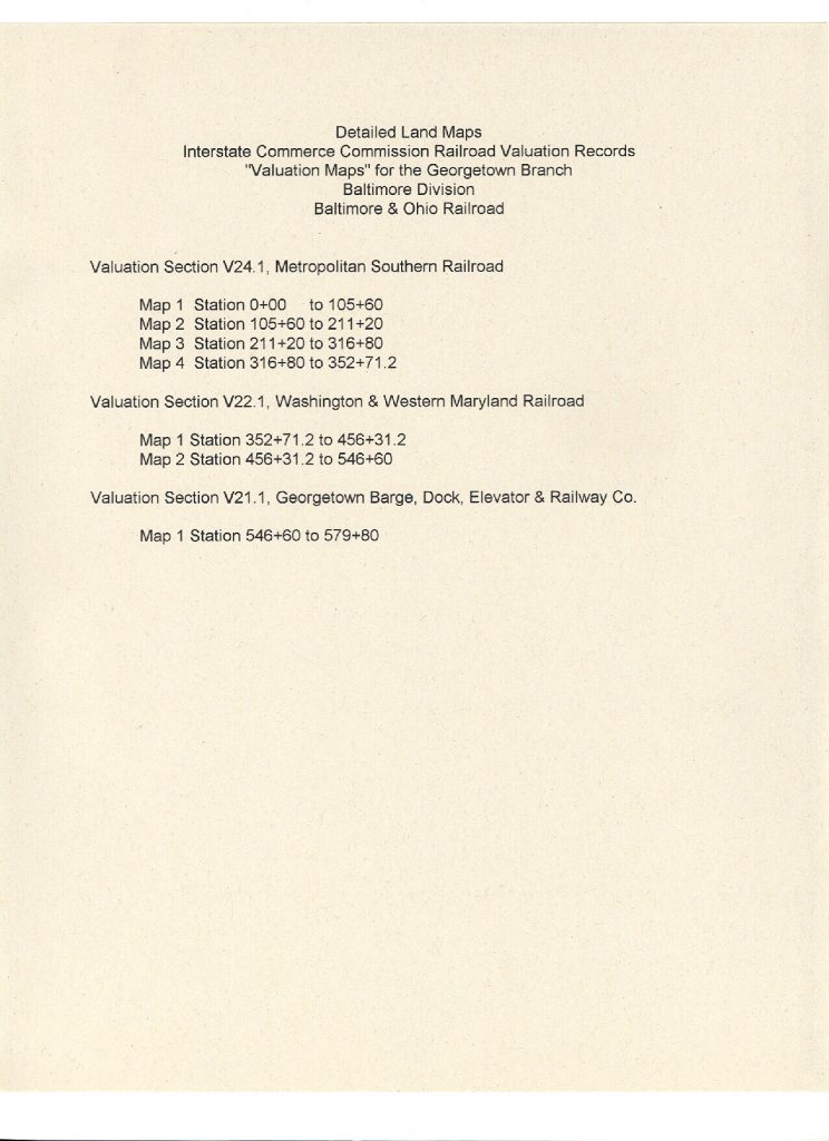
Valuation Section 24.1, Sheet 1 Published June 30, 1918. This covers Georgetown Jct. to Connecticut Ave. There is a ton of new info on this map! No sidings at the junction, sidings at Rock Creek Bridge (at each end) and a lot of detail at Chevy Chase! Wow!
Valuation Section 24.1 Published May, 1938. Also covers the area around Georgetown Jct. Not sure about this map. It shows a much wider perspective and has some markings near Silver Spring, probably regarding land ownership.
Here’s hoping they publish more in the future. Let me know if you see any!
Here is a list of the valuation maps that pertain to the GB.
After wrapping up the curved turnout build, I haven’t been back to the layout much over the last couple weeks. A few things have happened, so in the interest of momentum, I’ll share them here.
Last Fall I inherited an old Digitrax Super Empire Builder starter set, which is about 15 years old, from an old friend. This allowed me to switch from DCC++ to Digitrax for my main DCC system. (I’ve preserved my DCC++/JMRI/RPi setup for use as a programming and testing platform.) The Digitrax DT300 throttle that came with the set appeared to have been a victim of the capacitor plague and Digitrax had some sort of warranty repair program for repairing it. It will be going back to Digitrax for the repair soon. (they are just now getting back on track after being ravaged by hurricane Michael last year.)
So far, I have been using my backup throttle, an old UT-1 which I purchased about 17 years ago so I could run trains on the old MCMR club layout. The layout was gone shortly after I purchased it and I have never really had much use for it. With my new Digitrax system, I finally do! Since earlier in the Winter when I picked up the Digitrax system, I’ve used the UT-1. It works fine for running stuff around and testing it but I have been plugging it directly into the DB150 which means I can only use the throttle at one end of my long room. So, this weekend I decided to make some LocoNet cables. I have had some old inherited Cat5 cable that was left over from the old club storage area and some 6-pin RJ12 connectors and the proper crimping tools stashed away. I broke everything out and sat on the couch and did some crimping while watching TV with the wife. It went well. I had a bit of a re-learning curve as I figured out the process again. I attempted to use the cutter/stripper on the tool I have, but it would slice too much insulation and into the wires damaging them. I ended up using an X-Acto knife to carefully cut back the insulation. I also realized that my vision requires the use of glasses and an opti-visor to really get the wires correct!
The Digitrax LT1 tester proved to be tricky, as well. I read through the directions but I must have skimmed the part that said you must have a throttle plugged in for it to work correctly. (thank you Tom M. for helping me figure this out!) Anyway, once I got that working, the cables checked out and I hooked them up to a couple of the old Loy’s Toys cab bus fascia panels I have, and voila! I could now plug in my throttle at various spots around the room. Worked fine.
Lastly, I had a little bit of fun with some non-DCC locos I have collected over the years. I decided to put some basic decoders I have laying around into these engines and see if they will run. I fired up the DCC++/JMRI system and got to testing. I managed to get my Athearn Genesis 2-8-2 USRA light mikado and my Life-Like Proto2000 S1 up and running. I couldn’t fit the S1 shell back on and in doing some online research I found that these locos have a critical flaw that needs attention before the decoder can be properly installed. That will be next on my list.
So that’s it for now. Spring is here and thus my time in the layout room is being challenged by chores, yard work and other fun things. I’m hoping that I can continue as I really do have some great momentum right now. I visited my friend Kelly yesterday and saw his Georgetown layout which is really coming along nicely! He is modeling the area of G-town from the Aqueduct bridge to the “new yard” at Wisconsin Ave, with plans for expansion. Very cool!
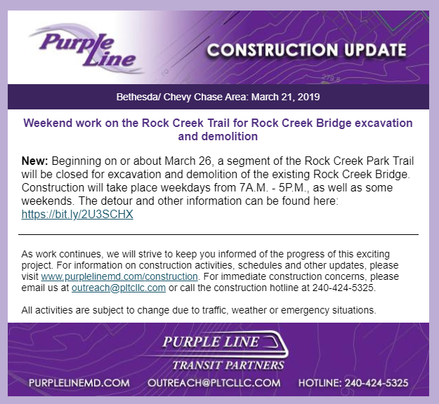
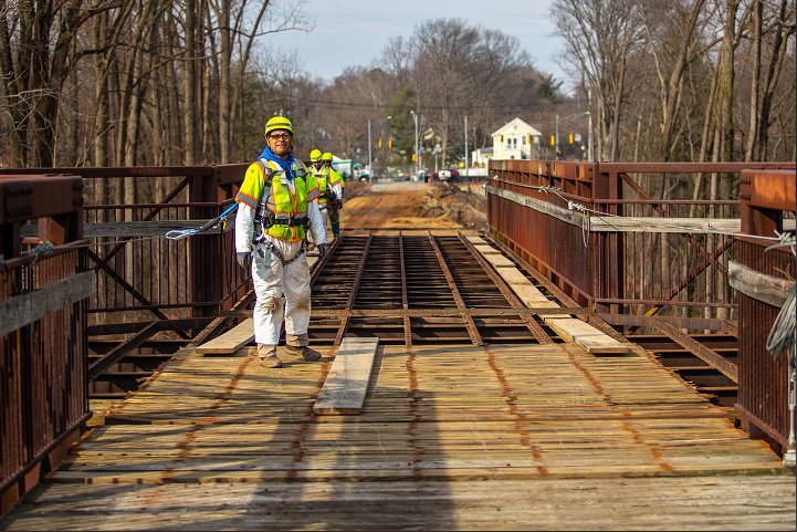
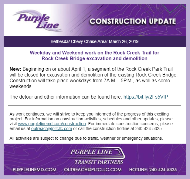
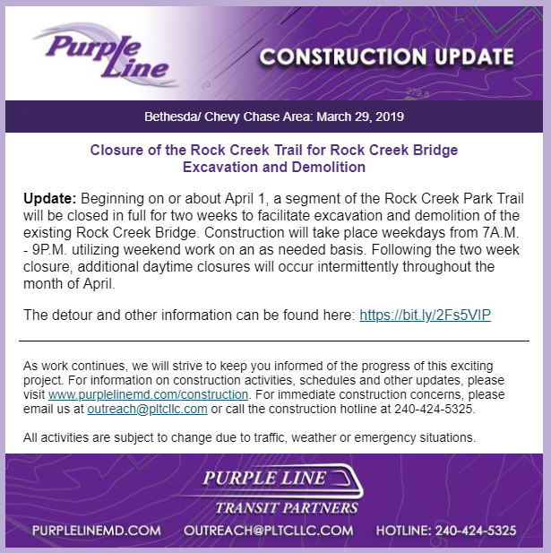
The bell is tolling for the Rock Creek trestle. The Purple Line has announced that beginning on March 26, demolition will begin as they remove the path across the top and then begin demolishing the trestle itself. Already the wood planking atop the trestle is being removed.
Photo from @PurpleLineMD
I am hoping to visit the site to witness some of the demolition. It’s heartbreaking to read about. RIP.
A bit of housekeeping: I’ve added a large set of photos from an exploration trip I did with Kelly R. on the GB back in 2015 to my Gallery. These photos were previously up on my Flickr page only but now you can view them in my Gallery. Enjoy!
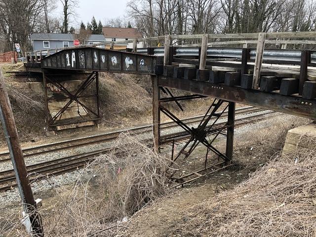
As most of you will know, the bridge which crosses the B&O’s Metropolitan Branch and Georgetown Branch lead at Georgetown Junction is slated to be torn down. The sides of the bridge, which once belonged to a turntable, are to be saved and placed along a new stretch of the Capital Crescent Trail, which is nice. The bridge was constructed at some point around 1918 and has seen several refurbishments over the years. Much of the support structure rusted away over the years and as such the bridge has been condemned for the last year or two. Thankfully, it was recently re-opened to pedestrian traffic.
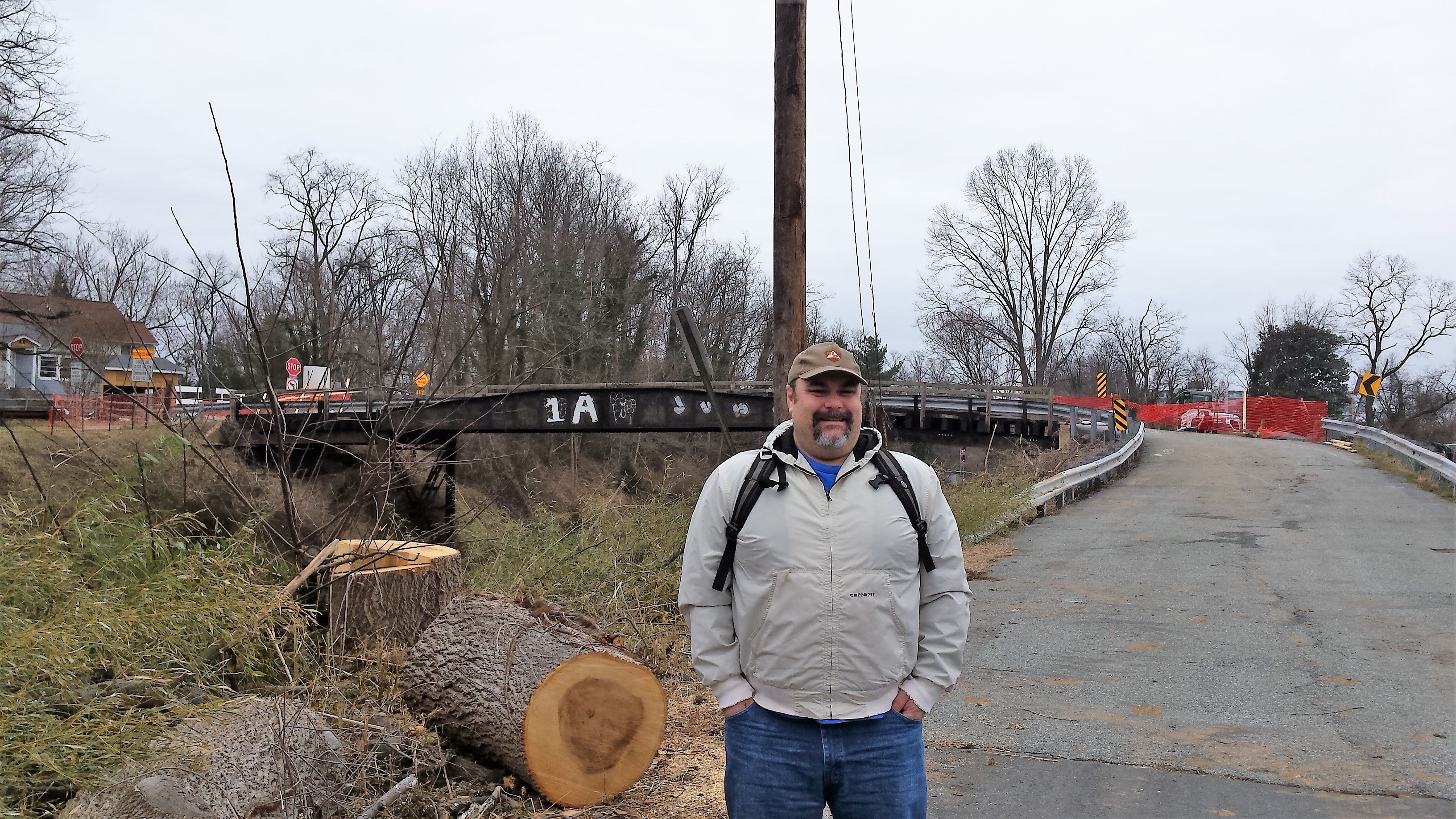
Here I am on a chilly Sunday posing in front of the Talbot Ave. bridge. It snowed a bit while we were there. Note the giant logs laying on the ground; evidence of the brush and tree clearing the Purple Line folks are doing. Photo by Greg C.
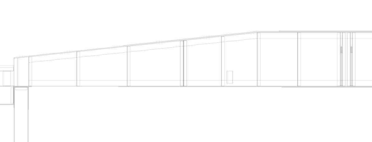
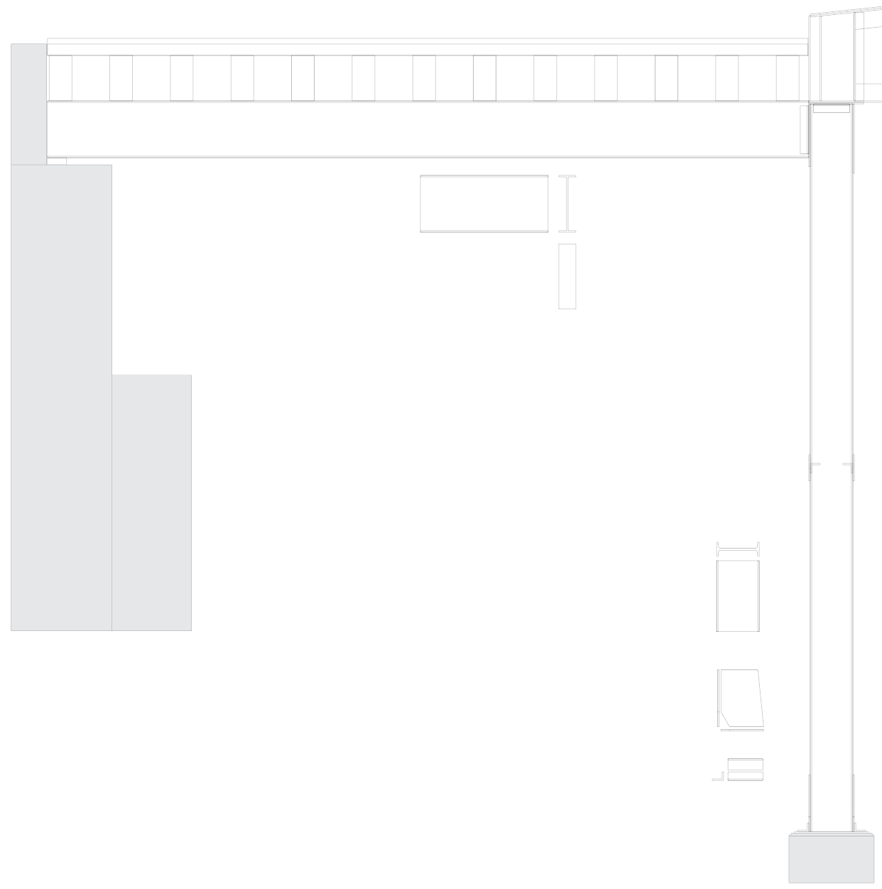
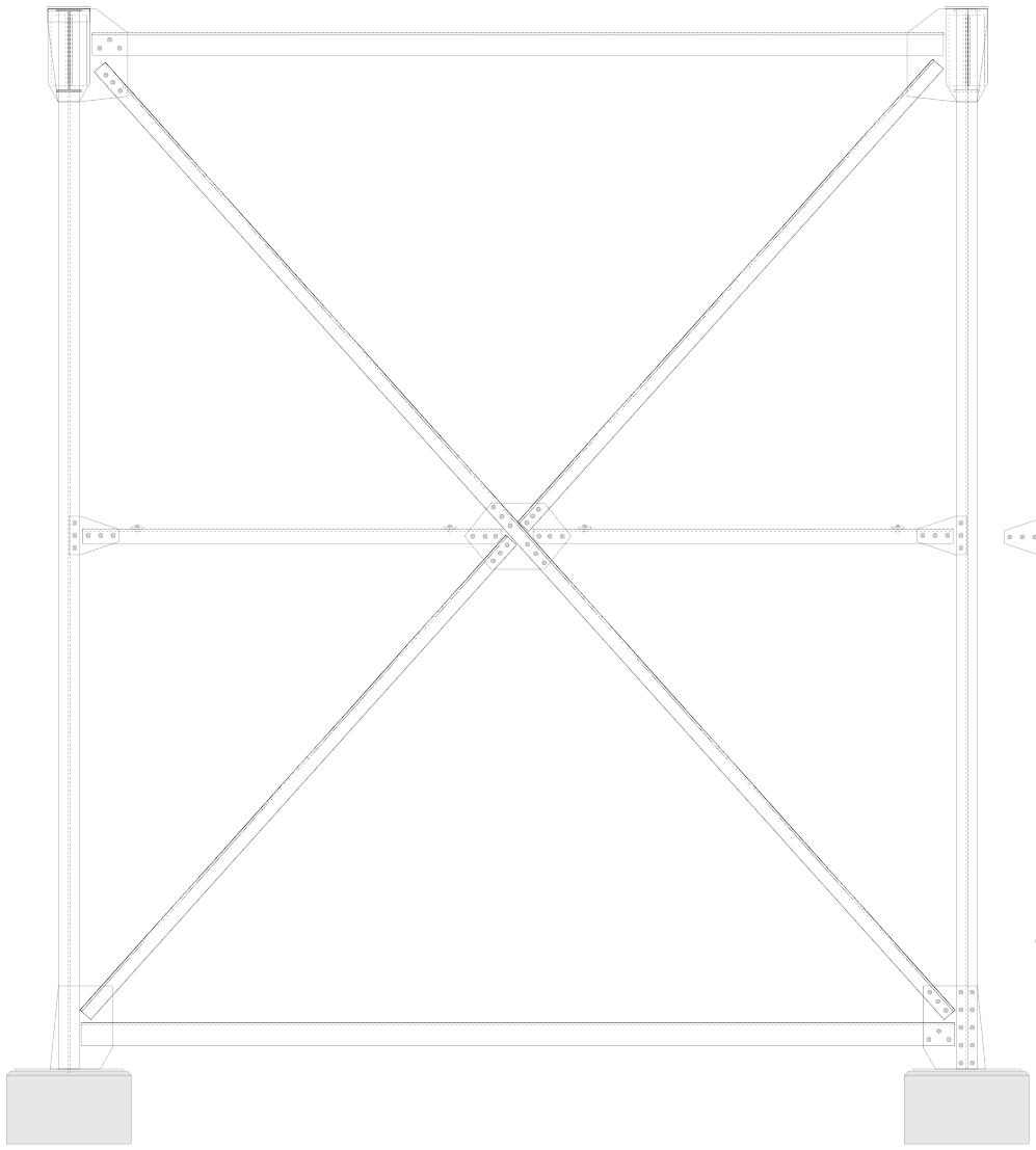
Greg C. and I spent a morning at the bridge documenting it both with a measuring tape and with a camera. All in all, it was a very successful trip and I feel confident that I have enough data to accurately model the bridge in HO scale for my layout. Unfortunately, the model will have to be modified a bit to fit in my space, but I plan on being as accurate as I can. I think once complete, it will be a really neat model. Here are a few a sneak peeks at the drawing I am developing of the bridge structure:
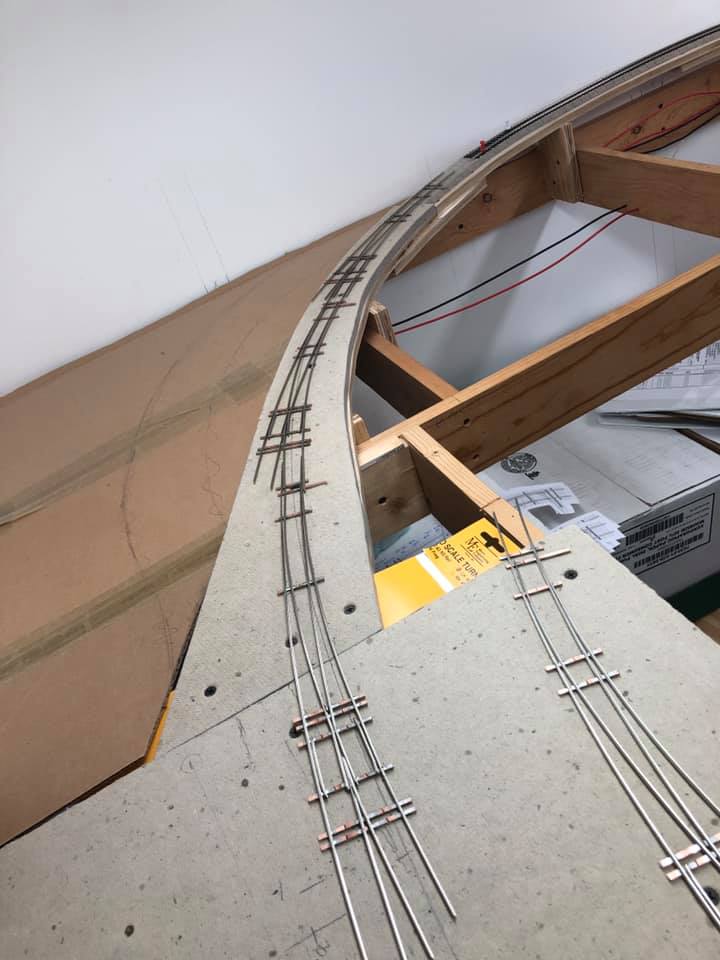
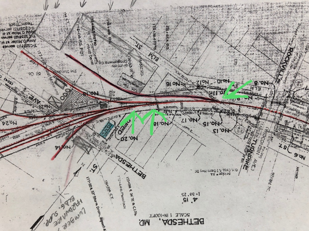
The three turnouts in place for the track coming into Bethesda. Not the extra curved turnout on the right.
After building my first curved turnout a couple weeks ago I decided to build the next two to complete the track coming into Bethesda. I spent several hours over the weekend putting these together. When all three were done, I set them in place and realized I didn’t like how they worked. The first one was too tight of a radius. Hmmm… the only solution was to build one MORE turnout! This one a #10 LH with a 60″ OR and 46″ IR. It took me a few more hours to complete as I don’t have a FastTracks PointForm jig for a #10 turnout, only #8. So I used that and filed them down further to get the clearance I needed. Improvise. Adapt. Overcome… yeah.
Closeup of the curved turnouts.
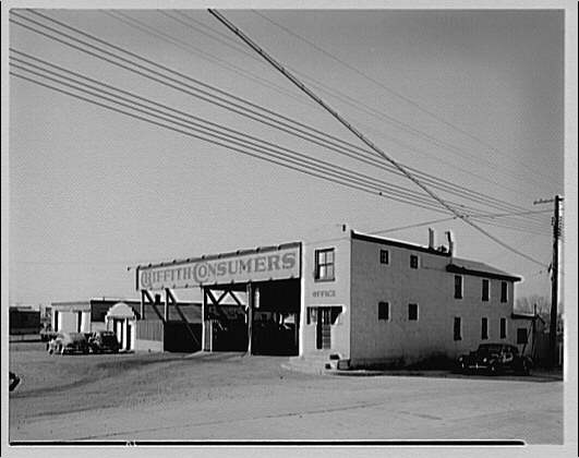
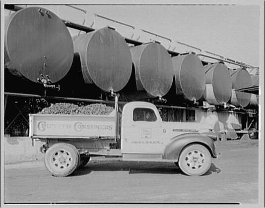
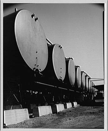
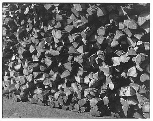
Putting together the turnouts has been a tremendously rewarding experience and I take a lot of pride in how they turned out. I still have a bit of work to do with them, specifically I need to cut gaps, test continuity, fit them in place on the layout, paint, weather, install ties and wiring. Oh, and switch machines. *phew!* I’ll also need to modify the benchwork for the first siding which branches off at the start of the curve. This will be for the Griffith Consumers Co. coal & oil facility, which you can see here in this 1949 aerial view on NETR Historic Aerials. I will add a bit of a wing of plywood and Homasote subroadbed and then drop down for the coal unloading trestle. Ideally this facility will receive 2-3 40′ cars of fuel oil and coal. Here are some random LoC photos of the facility there. Unfortunately I don’t have a great shot of the trestle.
Horydczak, T., photographer. Griffith Consumers Co. Yard at Bethesda for Griffith Consumers Co. Bethesda Maryland, None. ca. 1920-ca. 1950. [Photograph] Retrieved from the Library of Congress, https://www.loc.gov/item/thc1995000330/PP/. Horydczak, T., photographer. Griffith Consumers Co. Coal truck of Griffith Consumers Co. Bethesda Maryland, None. ca. 1920-ca. 1950. [Photograph] Retrieved from the Library of Congress, https://www.loc.gov/item/thc1995000332/PP/. Horydczak, T., photographer. Griffith Consumers Co. Oil tanks of Griffith Consumers Co. Bethesda Maryland, None. ca. 1920-ca. 1950. [Photograph] Retrieved from the Library of Congress, https://www.loc.gov/item/thc1995000331/PP/. Horydczak, T., photographer. (1947) Griffith Consumers Co. Coal pile in Bethesda, Maryland for Griffith Consumers Co. Bethesda Maryland, 1947. Sept. 18. [Photograph] Retrieved from the Library of Congress, https://www.loc.gov/item/thc1995000364/PP/. Horydczak, T., photographer. (1947) Griffith Consumers Co. Wood pile in Bethesda, Maryland for Griffith Consumers Co. Bethesda Maryland, 1947. Sept. 18. [Photograph] Retrieved from the Library of Congress, https://www.loc.gov/item/thc1995000365/PP/.
This newsreel footage has some really neat, yet very brief shots of Georgetown taken from the Memorial Bridge. You have to look hard, but you get a few really cool views of the dusty, smoky, dirty section of town off in the distance. Awesome find!
Memorial Bridge in 1932 with views of Georgetown in a few spots.
This photo had to have been taken around 1964, as I believe the Air Rights building (visible under construction in the distance) was completed in 1966. S2 9023 was built between 1943-48. I’m not sure of its original three digit number. The B&O Freight Station is visible to the left of the cab and the engine is sitting on the main, just past Bethesda Ave. I stumbled on this photo while looking at the B&O Diesel Roster on North East Rails. Photo by Bud Laws.
So all of my modeling life I have wanted to hand lay track. My father was a member of the TSC (Transportation Systems Center (the Volpe Center)) model railroad club back in the late 70s/early 80s. As a kid, I visited innumerable times. A third of the layout ended up in my basement when the club lost their lease. The layout was built with plywood and L-girder benchwork. All of the track was hand laid on lath. (thin strips of wood, kerfed for curves) I marveled at the robust hand-laid stuff, as back then everything was Atlas Snap-Track for me. But the seed was planted. I made a few attempts as a lad to hand lay track but it was usually heavy-handed and ended up with split ties and out-of-gauge rails. Oh well.
Fast forward to last week and my first attempt at hand laying track: a curved turnout, naturally! The impetus for this decision came after much trial and error of fitting turnouts a the northern throat of the Bethesda yard. The prototype arrangement in the 1940s included three turnouts; the first to Griffith Consumers (coal, oil), the second to various warehouses and merchants, and the third would diverge to the passing siding and other industries branching of further.
Here are the three turnouts I want to model.
I wrote about this on the blog a bit earlier. The curve is compound, going from a tighter to a broader radius. Initially I was planning on using a couple curved Micro Engineering #6 turnouts, but put this on hold while I worked on laying track to the area where these turnouts will go. Once I arrived there (to Bethesda) I realized that the ME turnouts just wouldn’t do. The “main” would be passing through the diverging route of these #6 turnouts. This proved to look very wonky and nigh impossible for my Precision Scale B&O Q1c mikado steam loco. It would have none of these sharp curves. There went that idea. I met with Matt R. and we went over a few options. I tested out every commercial curved turnout that I could get my hands on and nothing came close. What I needed was a few custom turnouts, either built in place or custom designed. I started to get nervous about hand building them. I spoke with friends from my model RR club who all encouraged me, offering tools and supplies to get me on my way. (great bunch of guys!) I reached out to a few custom turnout builders who gave me various prices (some very reasonable, some not-so) and I decided that was the way to go. At the same time I realized that I didn’t have the money saved up for this path forward and if I didn’t get these turnouts in it would effectively halt track work on the layout until I did. I did not like this idea. I had to give hand laying a try.
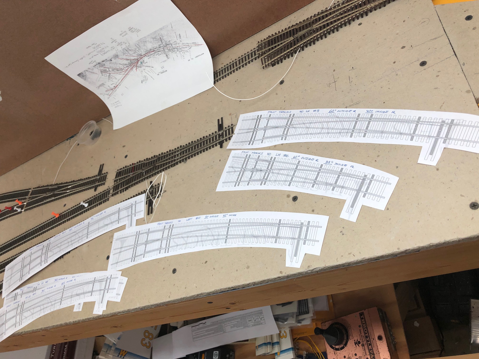
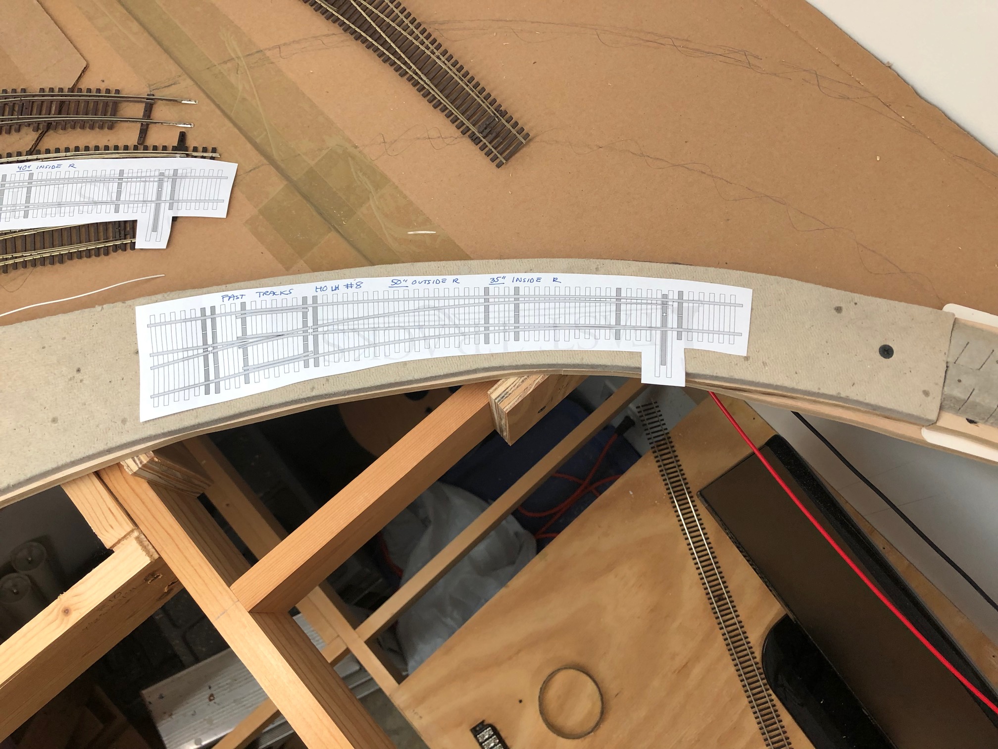
I printed out a few templates from the FastTracks website to play around with. They have templates of all of their turnouts available on their website for free to download. They are excellent for test-fitting turnouts on the layout!
A few of the FastTracks templates I used.
I then played around with fitting them on the layout in the spot where the curves will go.
Trial and error.
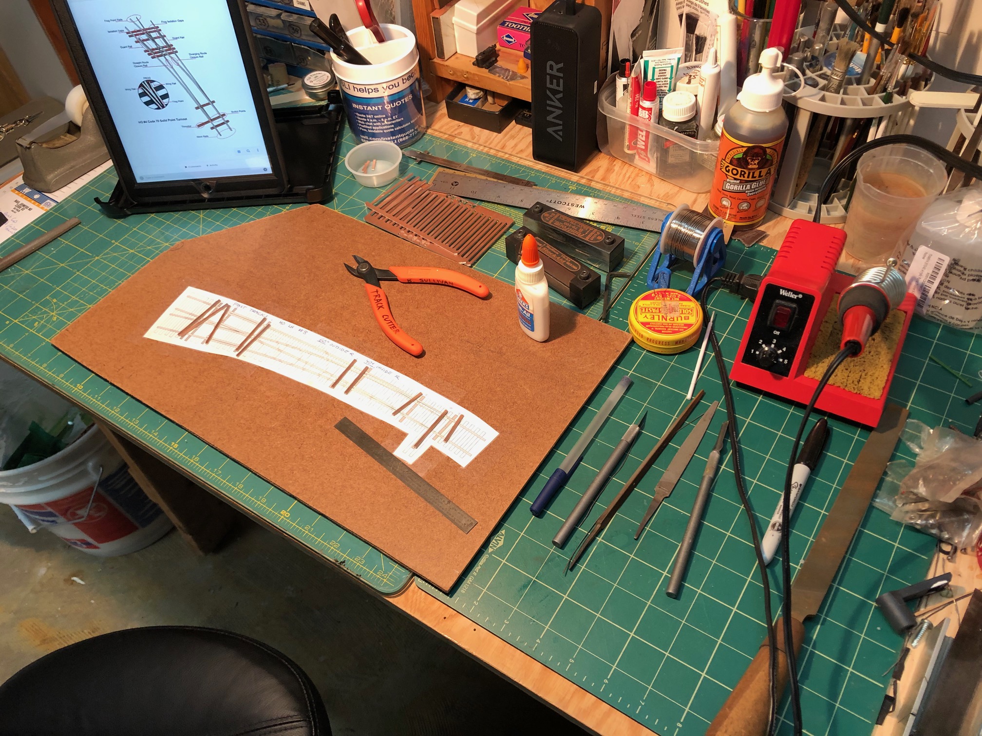
Once I found three templates that worked well together (remember, this is a tightening compound curve) I decided to give scratch building the turnout a try. I had previously ordered up some FastTracks Copperhead Turnout-lenth ties in preparation for this eventuality. Matt R. generously lent me his FastTracks C70-100 PointForm and C70/83 StockAid tools. (and gave me a demo and the pro tip of using a vise to hold the tools while filing; this worked beautifully) Everything else I had on hand already; rails, ties, solder, flux, tools, etc. I used a spare flat piece of Masonite and taped the template carefully and firmly down with Scotch tape. I gathered every tool I could imagine needing on the workbench and set up.
My work space
I had watched several videos on YouTube of folks building curved turnouts, but the most impressive and educational was this one by the late MMR Wolfgang Dudler. He wordlessly illustrates his technique for building the turnout in great detail and precision. I emulated this as I built my own, taking my time and trying my best to think ahead at every step. It paid off.
Here I’ve laid the copper ties in place and am preparing the rails.
I first cut the PCB ties to length and notched them per the template and then glued them to the template with a tiny bit of Elmer’s White Glue. I set a board and some weight on top while I spent the next 30-40 min forming and shaping rails. I used the FastTracks tools to form points and realized that they needed much more filing since this was such a broad curved turnout. This was done by hand using sandpaper laying on the table. I also used a smaller file to take off some larger areas. I basically followed along with the FastTracks how-to video and used the paper template as a guide. It came together beautifully.
Once all the filing/forming was done, I started by soldering the outer rails in place. I put weights on them as I worked. This held them in place for soldering. With patience, it goes fast. Just be sure that all the curves are where you want them. If you find that you don’t like a joint, hit it with the soldering iron and re-position it. It’s just that simple. Flux is essential. Check the gauge with your NMRA and tripod style track gauges. I also snagged a wheel set to test the flow through the turnout. If things need tweaking along the way, don’t be afraid to stop and work the problem out. Also don’t be afraid to re-cut a piece of rail. Having the turnout flow nicely is crucial for long-term operational quality. Here is a shot of the nearly-finished turnout:
My first scratch built curved turnout. It works!
I still need to cut gaps, install wood ties, file some solder that is fouling the points and finesse clearance at the frog a bit more. The truck rolls freely through all the routes and the NMRA gauge indicates that clearances are decent. This project took me a few hours of work. Being that it was my first (ever!) turnout and that I was learning as I went, I think I can cut the time down about 20% in the future. Regardless, I enjoyed the experience and will update the blog once I get the other two completed.
The Bethesda section of my layout should be completed over the next month or two, ideally. Stay tuned!