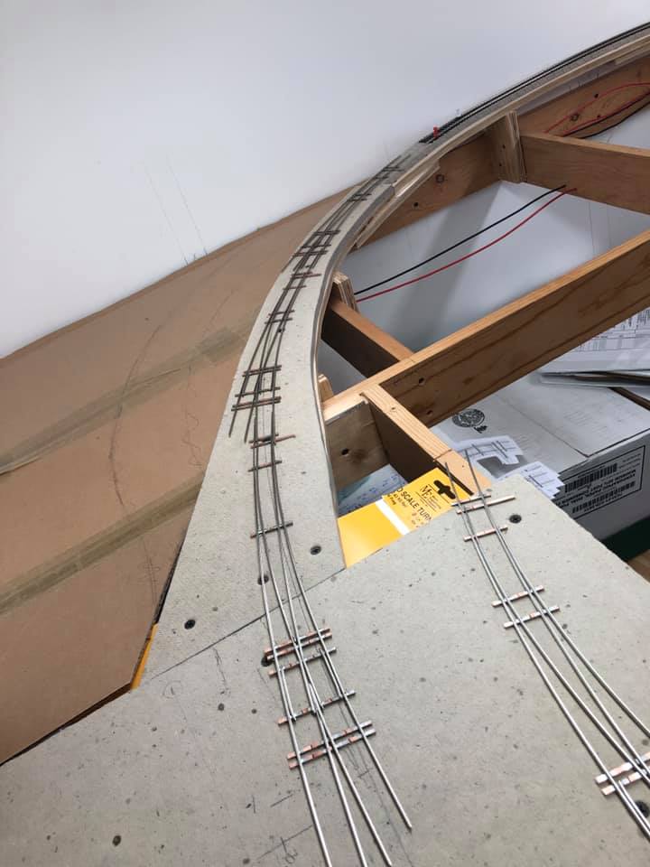
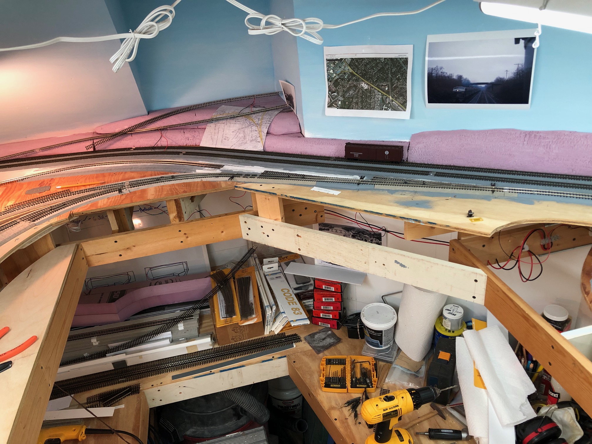
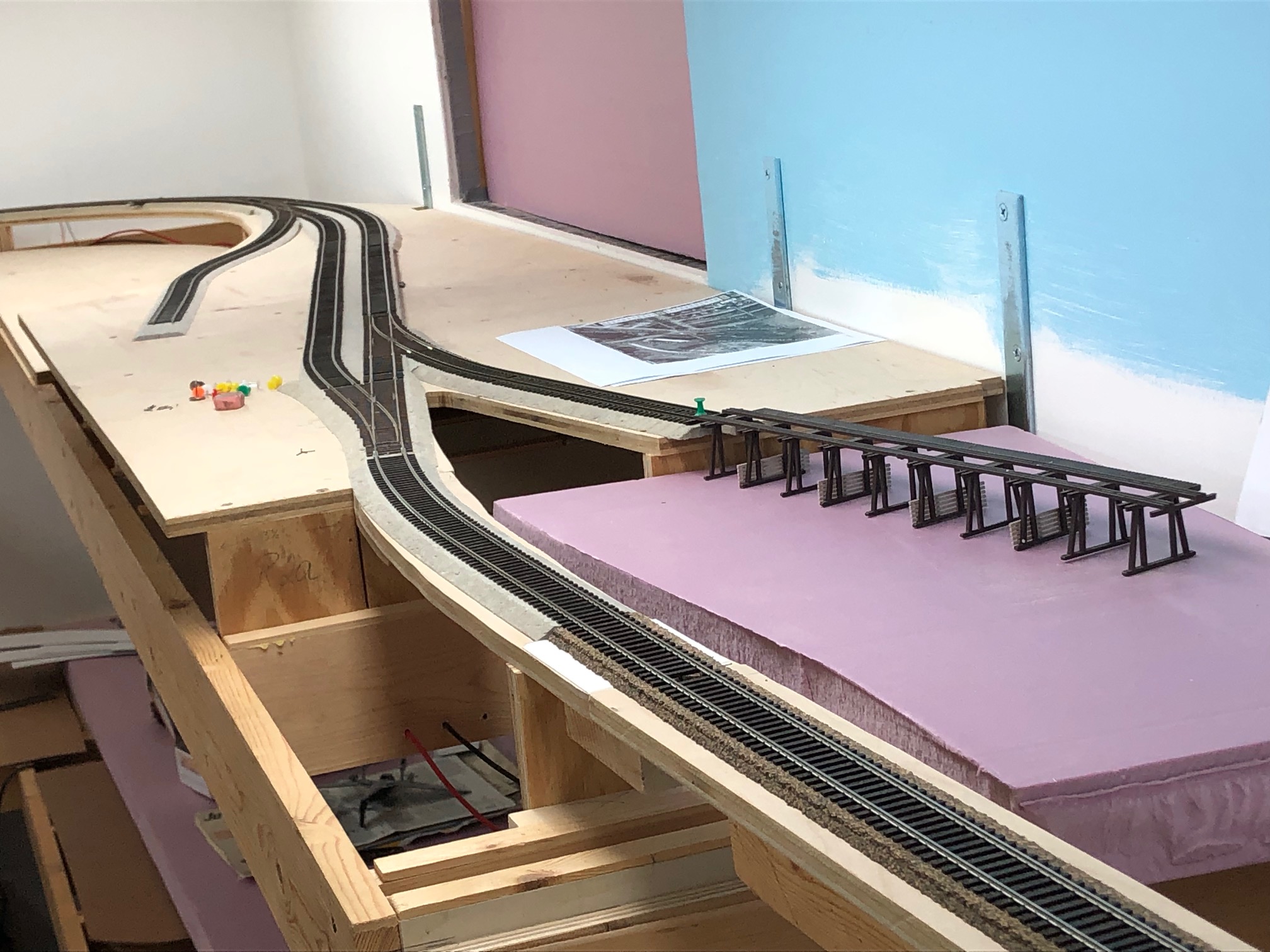
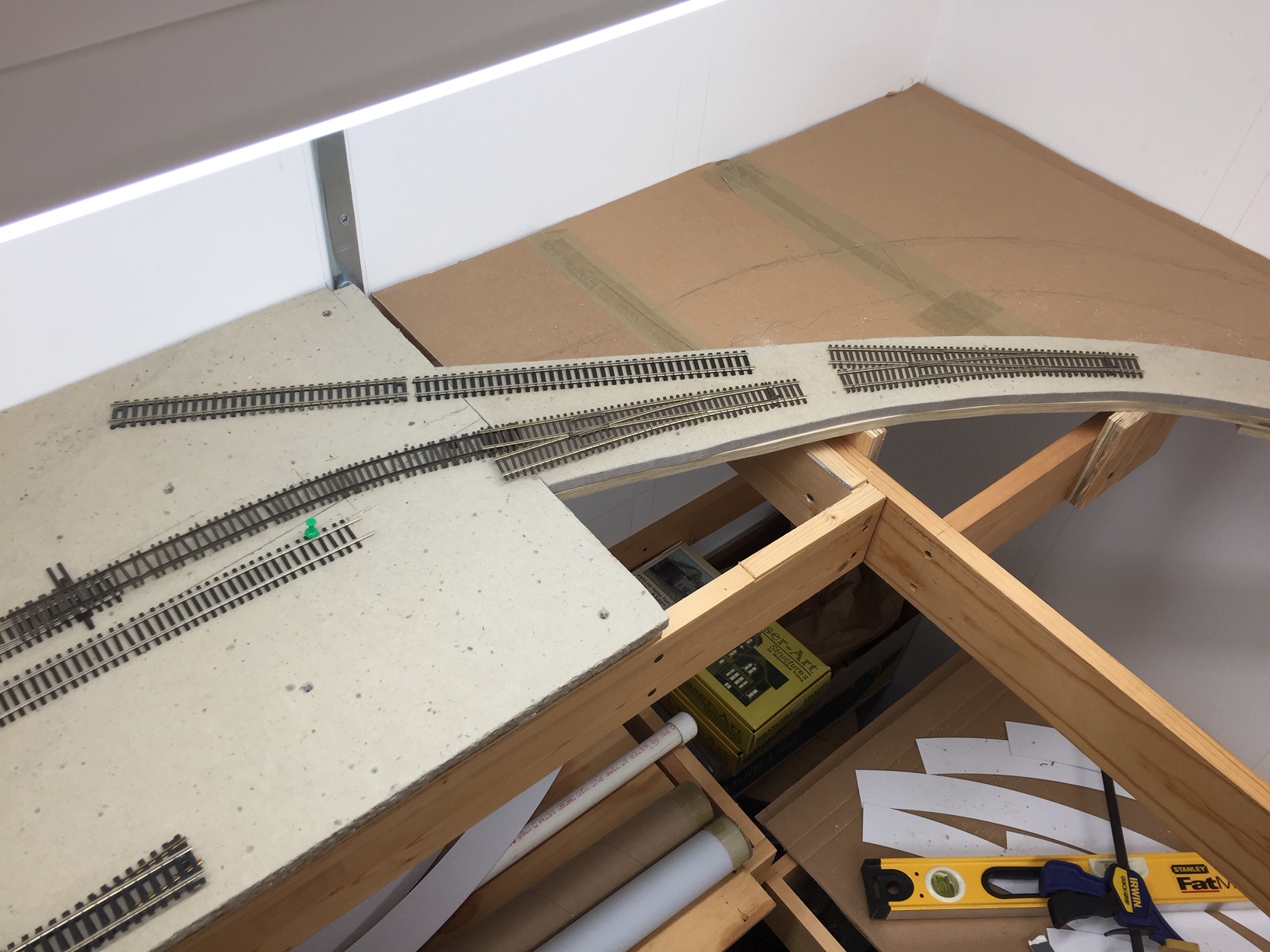
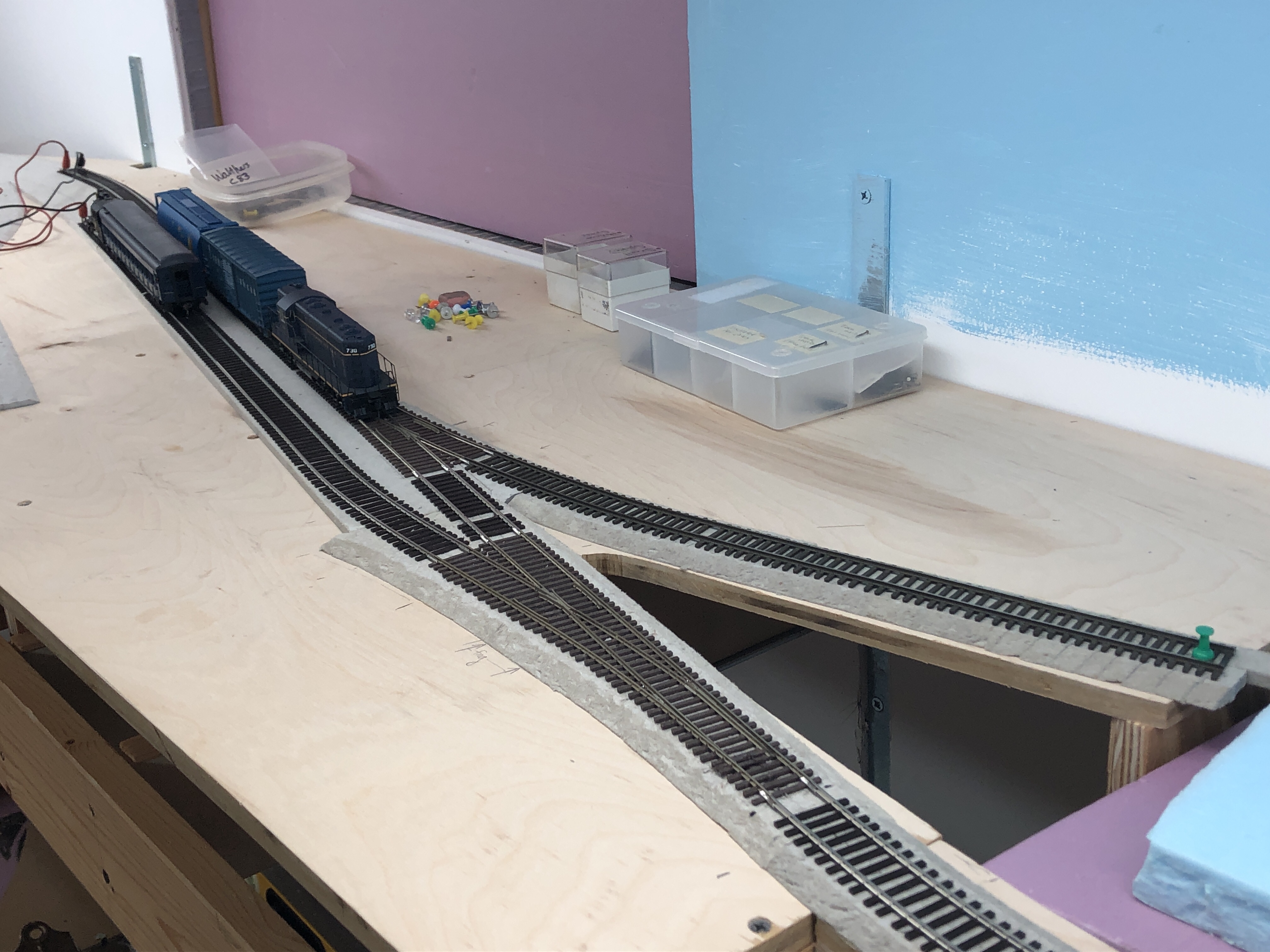
The three turnouts in place for the track coming into Bethesda. Not the extra curved turnout on the right.
After building my first curved turnout a couple weeks ago I decided to build the next two to complete the track coming into Bethesda. I spent several hours over the weekend putting these together. When all three were done, I set them in place and realized I didn’t like how they worked. The first one was too tight of a radius. Hmmm… the only solution was to build one MORE turnout! This one a #10 LH with a 60″ OR and 46″ IR. It took me a few more hours to complete as I don’t have a FastTracks PointForm jig for a #10 turnout, only #8. So I used that and filed them down further to get the clearance I needed. Improvise. Adapt. Overcome… yeah.
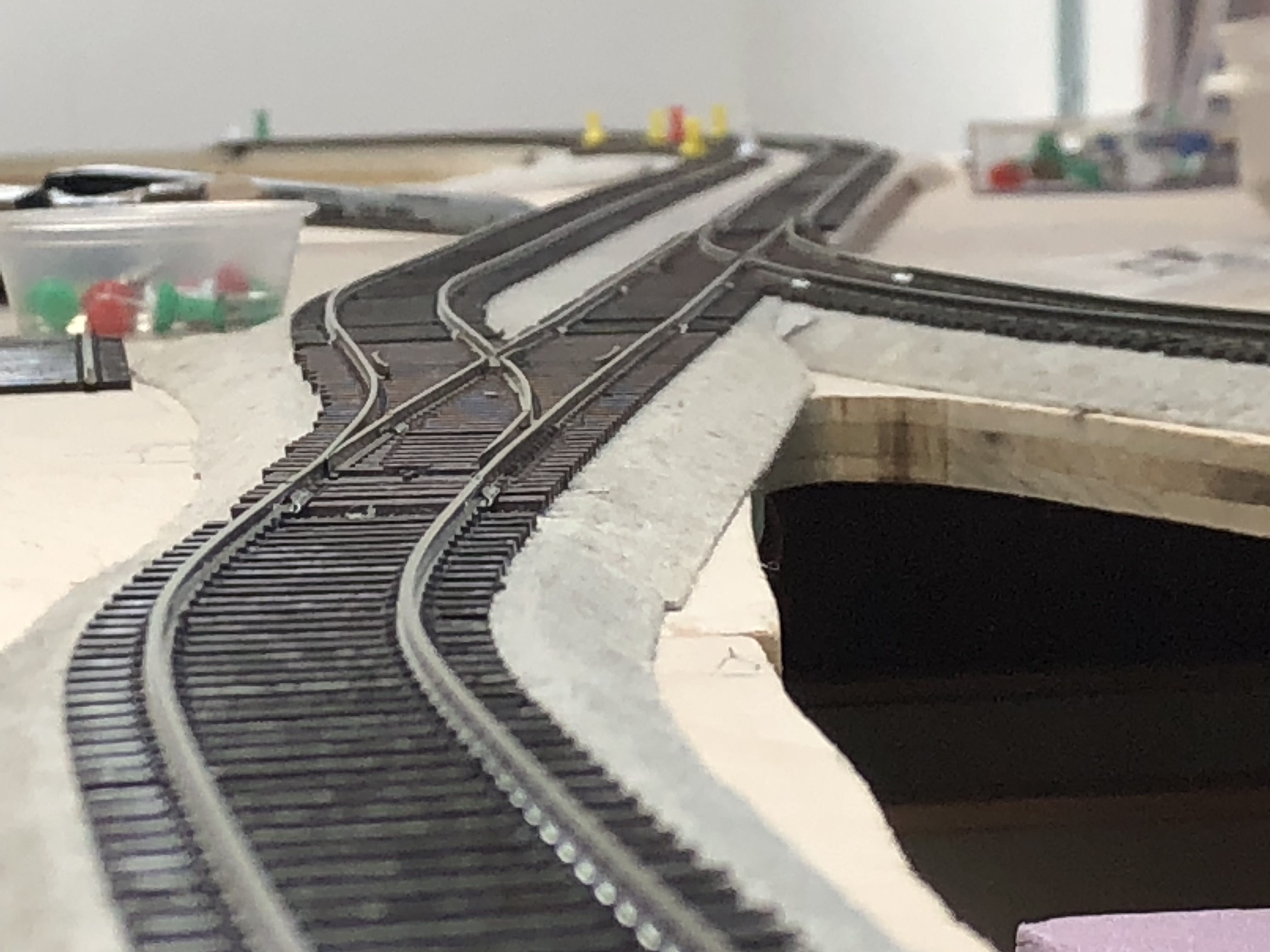
Closeup of the curved turnouts.
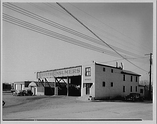
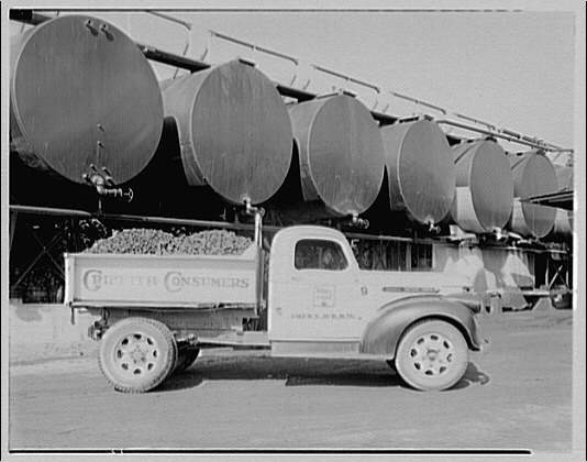
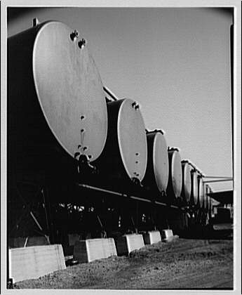
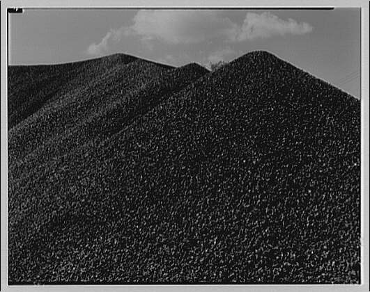
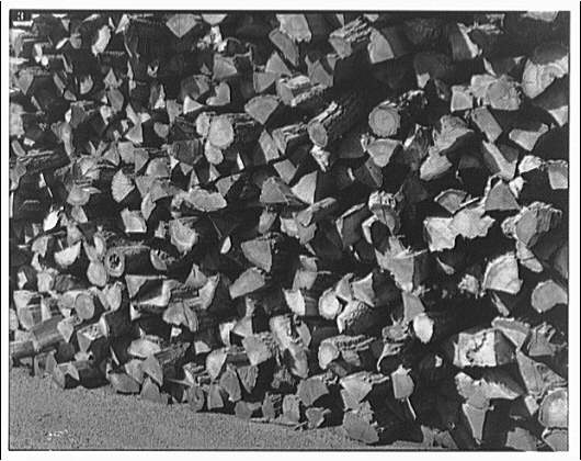
Putting together the turnouts has been a tremendously rewarding experience and I take a lot of pride in how they turned out. I still have a bit of work to do with them, specifically I need to cut gaps, test continuity, fit them in place on the layout, paint, weather, install ties and wiring. Oh, and switch machines. *phew!* I’ll also need to modify the benchwork for the first siding which branches off at the start of the curve. This will be for the Griffith Consumers Co. coal & oil facility, which you can see here in this 1949 aerial view on NETR Historic Aerials. I will add a bit of a wing of plywood and Homasote subroadbed and then drop down for the coal unloading trestle. Ideally this facility will receive 2-3 40′ cars of fuel oil and coal. Here are some random LoC photos of the facility there. Unfortunately I don’t have a great shot of the trestle.
Horydczak, T., photographer. Griffith Consumers Co. Yard at Bethesda for Griffith Consumers Co. Bethesda Maryland, None. ca. 1920-ca. 1950. [Photograph] Retrieved from the Library of Congress, https://www.loc.gov/item/thc1995000330/PP/. Horydczak, T., photographer. Griffith Consumers Co. Coal truck of Griffith Consumers Co. Bethesda Maryland, None. ca. 1920-ca. 1950. [Photograph] Retrieved from the Library of Congress, https://www.loc.gov/item/thc1995000332/PP/. Horydczak, T., photographer. Griffith Consumers Co. Oil tanks of Griffith Consumers Co. Bethesda Maryland, None. ca. 1920-ca. 1950. [Photograph] Retrieved from the Library of Congress, https://www.loc.gov/item/thc1995000331/PP/. Horydczak, T., photographer. (1947) Griffith Consumers Co. Coal pile in Bethesda, Maryland for Griffith Consumers Co. Bethesda Maryland, 1947. Sept. 18. [Photograph] Retrieved from the Library of Congress, https://www.loc.gov/item/thc1995000364/PP/. Horydczak, T., photographer. (1947) Griffith Consumers Co. Wood pile in Bethesda, Maryland for Griffith Consumers Co. Bethesda Maryland, 1947. Sept. 18. [Photograph] Retrieved from the Library of Congress, https://www.loc.gov/item/thc1995000365/PP/.
So all of my modeling life I have wanted to hand lay track. My father was a member of the TSC (Transportation Systems Center (the Volpe Center)) model railroad club back in the late 70s/early 80s. As a kid, I visited innumerable times. A third of the layout ended up in my basement when the club lost their lease. The layout was built with plywood and L-girder benchwork. All of the track was hand laid on lath. (thin strips of wood, kerfed for curves) I marveled at the robust hand-laid stuff, as back then everything was Atlas Snap-Track for me. But the seed was planted. I made a few attempts as a lad to hand lay track but it was usually heavy-handed and ended up with split ties and out-of-gauge rails. Oh well.
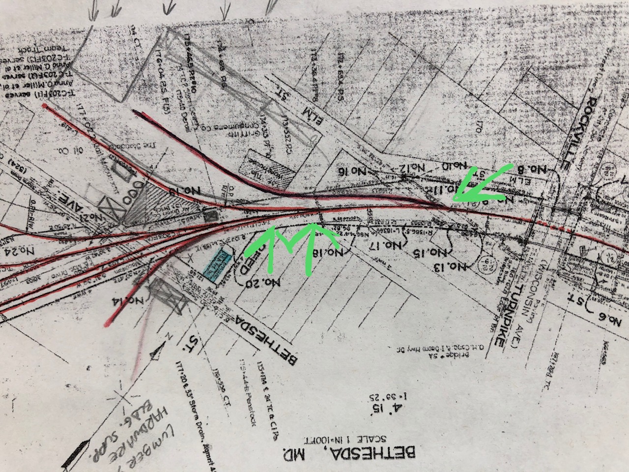
Fast forward to last week and my first attempt at hand laying track: a curved turnout, naturally! The impetus for this decision came after much trial and error of fitting turnouts a the northern throat of the Bethesda yard. The prototype arrangement in the 1940s included three turnouts; the first to Griffith Consumers (coal, oil), the second to various warehouses and merchants, and the third would diverge to the passing siding and other industries branching of further.
Here are the three turnouts I want to model.
I wrote about this on the blog a bit earlier. The curve is compound, going from a tighter to a broader radius. Initially I was planning on using a couple curved Micro Engineering #6 turnouts, but put this on hold while I worked on laying track to the area where these turnouts will go. Once I arrived there (to Bethesda) I realized that the ME turnouts just wouldn’t do. The “main” would be passing through the diverging route of these #6 turnouts. This proved to look very wonky and nigh impossible for my Precision Scale B&O Q1c mikado steam loco. It would have none of these sharp curves. There went that idea. I met with Matt R. and we went over a few options. I tested out every commercial curved turnout that I could get my hands on and nothing came close. What I needed was a few custom turnouts, either built in place or custom designed. I started to get nervous about hand building them. I spoke with friends from my model RR club who all encouraged me, offering tools and supplies to get me on my way. (great bunch of guys!) I reached out to a few custom turnout builders who gave me various prices (some very reasonable, some not-so) and I decided that was the way to go. At the same time I realized that I didn’t have the money saved up for this path forward and if I didn’t get these turnouts in it would effectively halt track work on the layout until I did. I did not like this idea. I had to give hand laying a try.
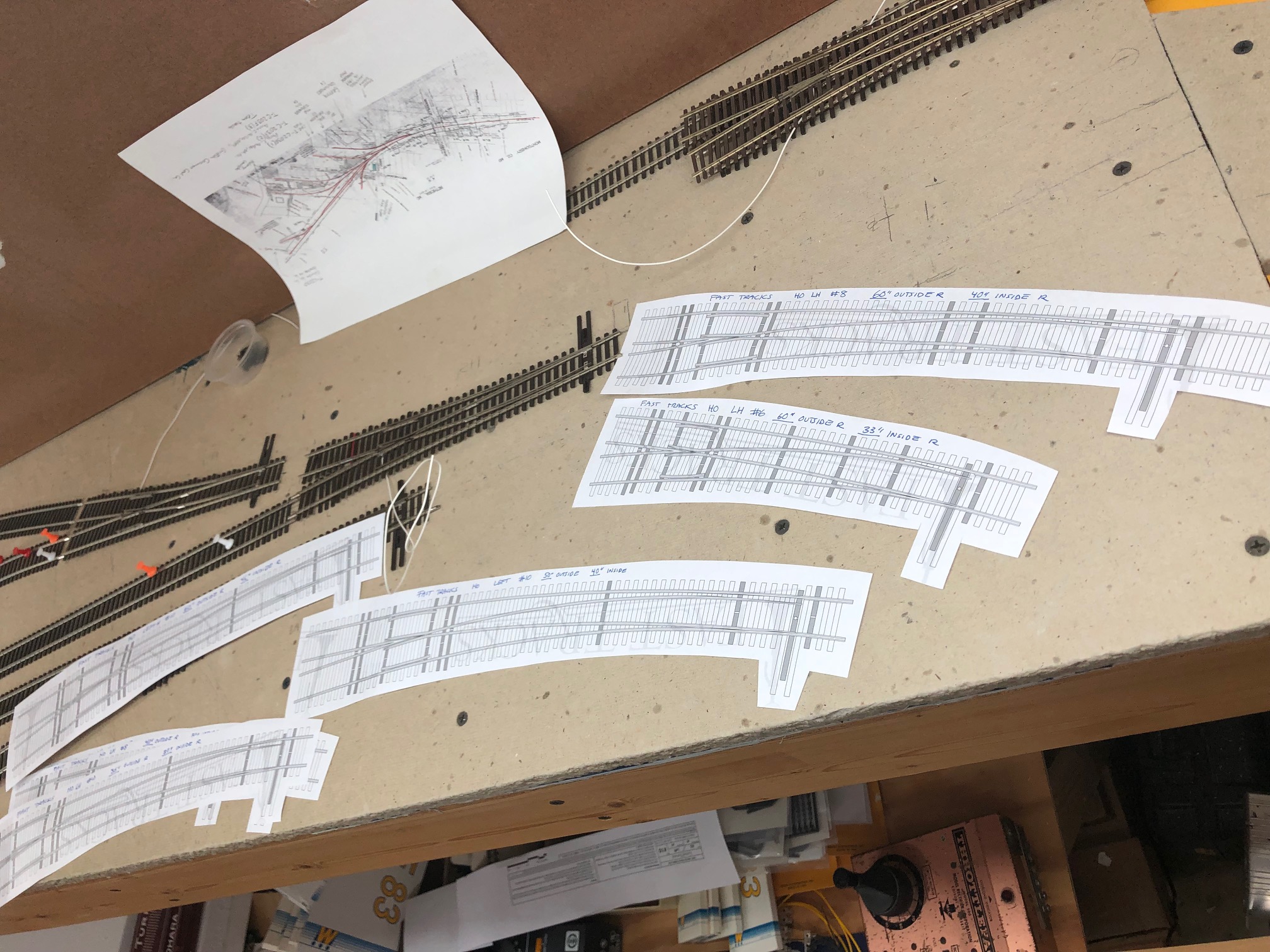
I printed out a few templates from the FastTracks website to play around with. They have templates of all of their turnouts available on their website for free to download. They are excellent for test-fitting turnouts on the layout!
A few of the FastTracks templates I used.
I then played around with fitting them on the layout in the spot where the curves will go.
Trial and error.
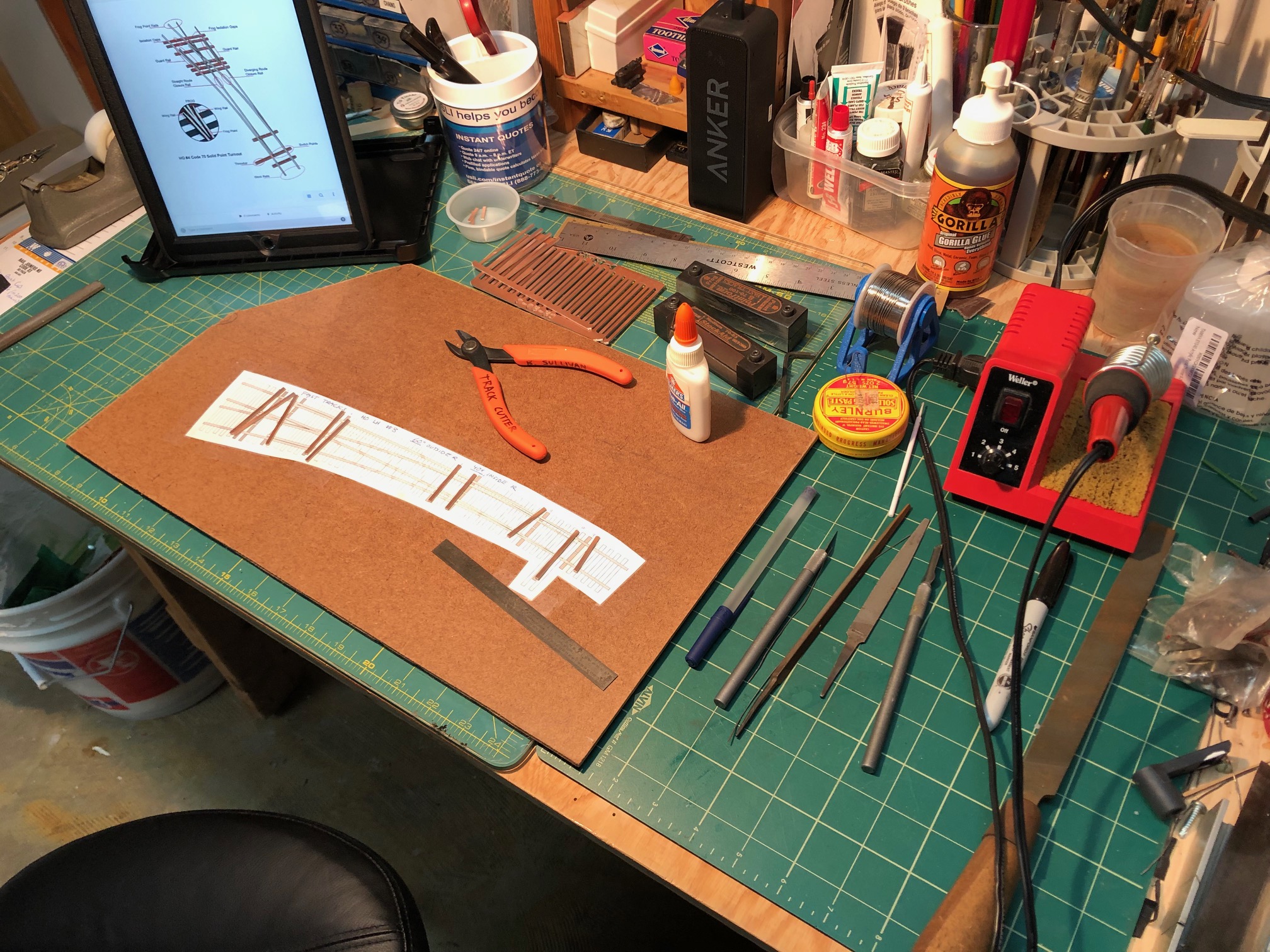
Once I found three templates that worked well together (remember, this is a tightening compound curve) I decided to give scratch building the turnout a try. I had previously ordered up some FastTracks Copperhead Turnout-lenth ties in preparation for this eventuality. Matt R. generously lent me his FastTracks C70-100 PointForm and C70/83 StockAid tools. (and gave me a demo and the pro tip of using a vise to hold the tools while filing; this worked beautifully) Everything else I had on hand already; rails, ties, solder, flux, tools, etc. I used a spare flat piece of Masonite and taped the template carefully and firmly down with Scotch tape. I gathered every tool I could imagine needing on the workbench and set up.
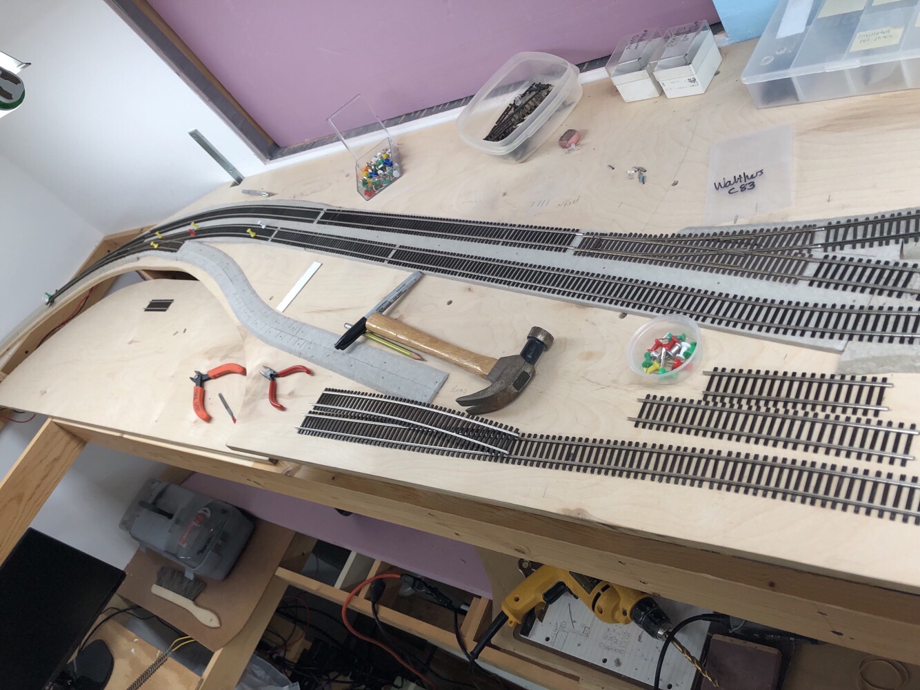
My work space
I had watched several videos on YouTube of folks building curved turnouts, but the most impressive and educational was this one by the late MMR Wolfgang Dudler. He wordlessly illustrates his technique for building the turnout in great detail and precision. I emulated this as I built my own, taking my time and trying my best to think ahead at every step. It paid off.
Here I’ve laid the copper ties in place and am preparing the rails.
I first cut the PCB ties to length and notched them per the template and then glued them to the template with a tiny bit of Elmer’s White Glue. I set a board and some weight on top while I spent the next 30-40 min forming and shaping rails. I used the FastTracks tools to form points and realized that they needed much more filing since this was such a broad curved turnout. This was done by hand using sandpaper laying on the table. I also used a smaller file to take off some larger areas. I basically followed along with the FastTracks how-to video and used the paper template as a guide. It came together beautifully.
Once all the filing/forming was done, I started by soldering the outer rails in place. I put weights on them as I worked. This held them in place for soldering. With patience, it goes fast. Just be sure that all the curves are where you want them. If you find that you don’t like a joint, hit it with the soldering iron and re-position it. It’s just that simple. Flux is essential. Check the gauge with your NMRA and tripod style track gauges. I also snagged a wheel set to test the flow through the turnout. If things need tweaking along the way, don’t be afraid to stop and work the problem out. Also don’t be afraid to re-cut a piece of rail. Having the turnout flow nicely is crucial for long-term operational quality. Here is a shot of the nearly-finished turnout:
My first scratch built curved turnout. It works!
I still need to cut gaps, install wood ties, file some solder that is fouling the points and finesse clearance at the frog a bit more. The truck rolls freely through all the routes and the NMRA gauge indicates that clearances are decent. This project took me a few hours of work. Being that it was my first (ever!) turnout and that I was learning as I went, I think I can cut the time down about 20% in the future. Regardless, I enjoyed the experience and will update the blog once I get the other two completed.
The Bethesda section of my layout should be completed over the next month or two, ideally. Stay tuned!
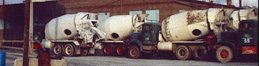
The Bethesda area of my layout will feature the Maloney Concrete plant fairly prominently. I would like to have a few trucks parked nearby and the correct color scheme is important. Unfortunately I don’t have any color images showing what vehicles they owned in the 1940s and 50s looked like but I do have a few from the late 1970s. These images were shared with me by Don Wetmore and thankfully have some of the Maloney fleet pictured in the background. There is some variance here, specifically in the wheels and front bumper and guard which shows most painted red and some painted white. Cab is painted a dark green. Frame, bumpers and some trim/wheels are red. Mixing apparatus, platforms and fuel tanks are white, overall. This is just a starting point and a generalization until I can get some better photos. Last week I picked up an Athearn Mack B concrete truck that I plan on respraying when I can find the time. 🙂
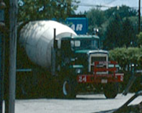
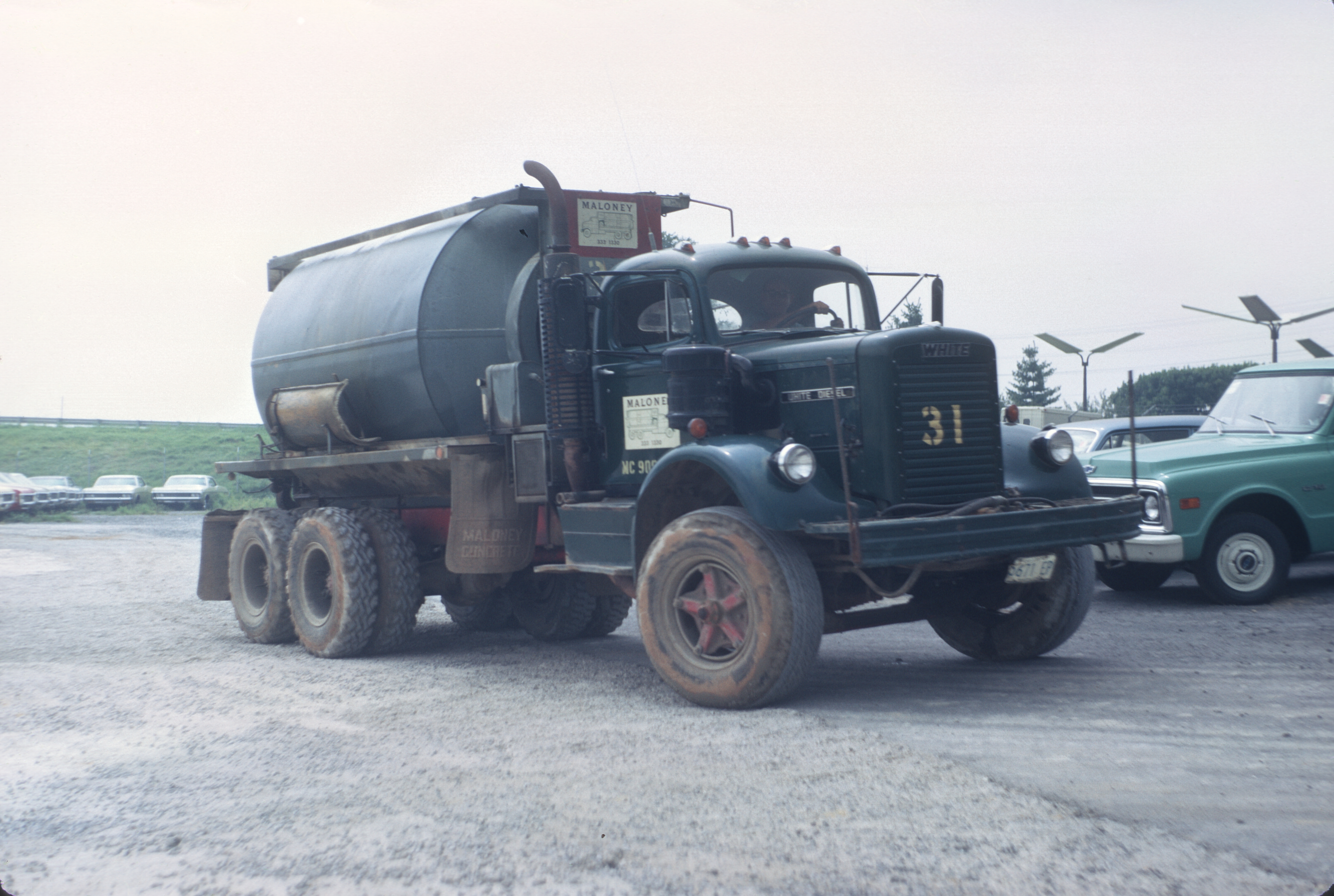
John King, local historian, modeler and railfan, reached out to me and shared a wonderful photo that he took back in 1969 which shows in GREAT detail a Maloney Concrete mixing truck! Here are the details:
John writes:
This was August, 1969 in Rockville at the intersection of MD 355 and Gude Drive. At the time this was the used car lot for Rockmont (now Ourisman ) Chevrolet. They were paving the storage yard with left over concrete. I was working there for a summer job so, needless to say, you know who got the task of smoothing the stuff out after it was dumped.
Maloney’s Rockville plant apparently had low clearances requiring this style truck. I remembered this style from when they delivered cement to our farm a few years earlier. Not sure if they used this type of ready mix truck at any of their other locations or not. I think there was a hatch on the side of the drum for loading the materials as opposed to both loading and unloading on the rear of the more modern style mixers. If nothing else, it confirms the green paint with red frame and wheels.
Also, note that the sign shows this type of truck, not the more modern ones.
August, 1969 – Route 355 and Gude Dr, Rockville, MD – Maloney Concrete mixing truck #31. Photo by John King.
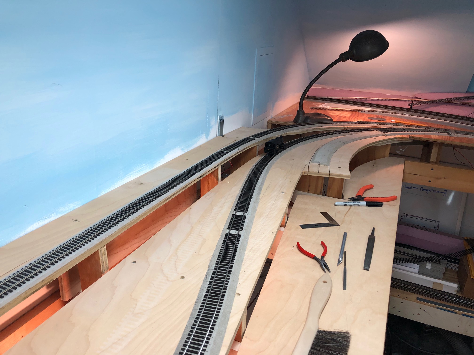
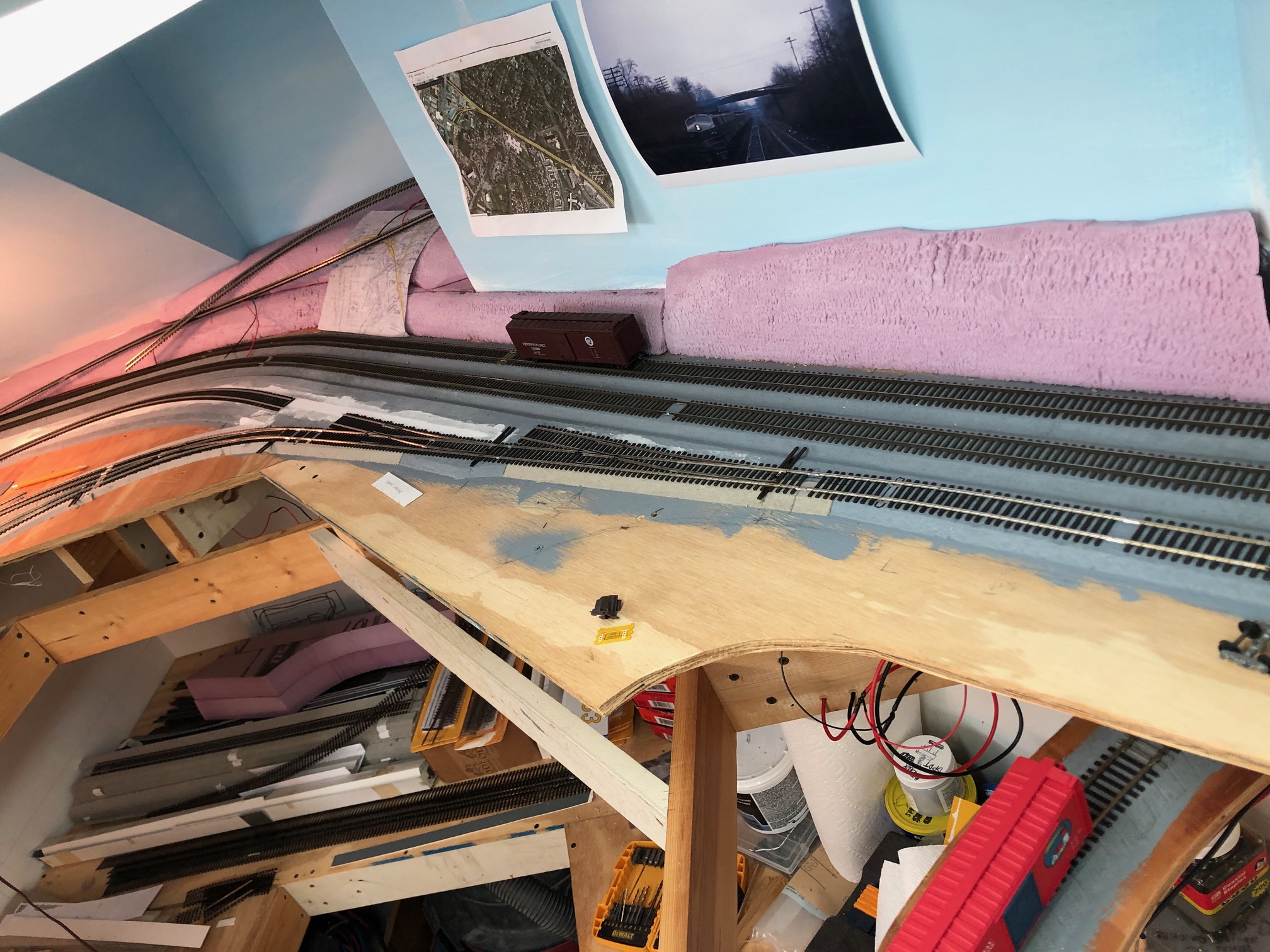
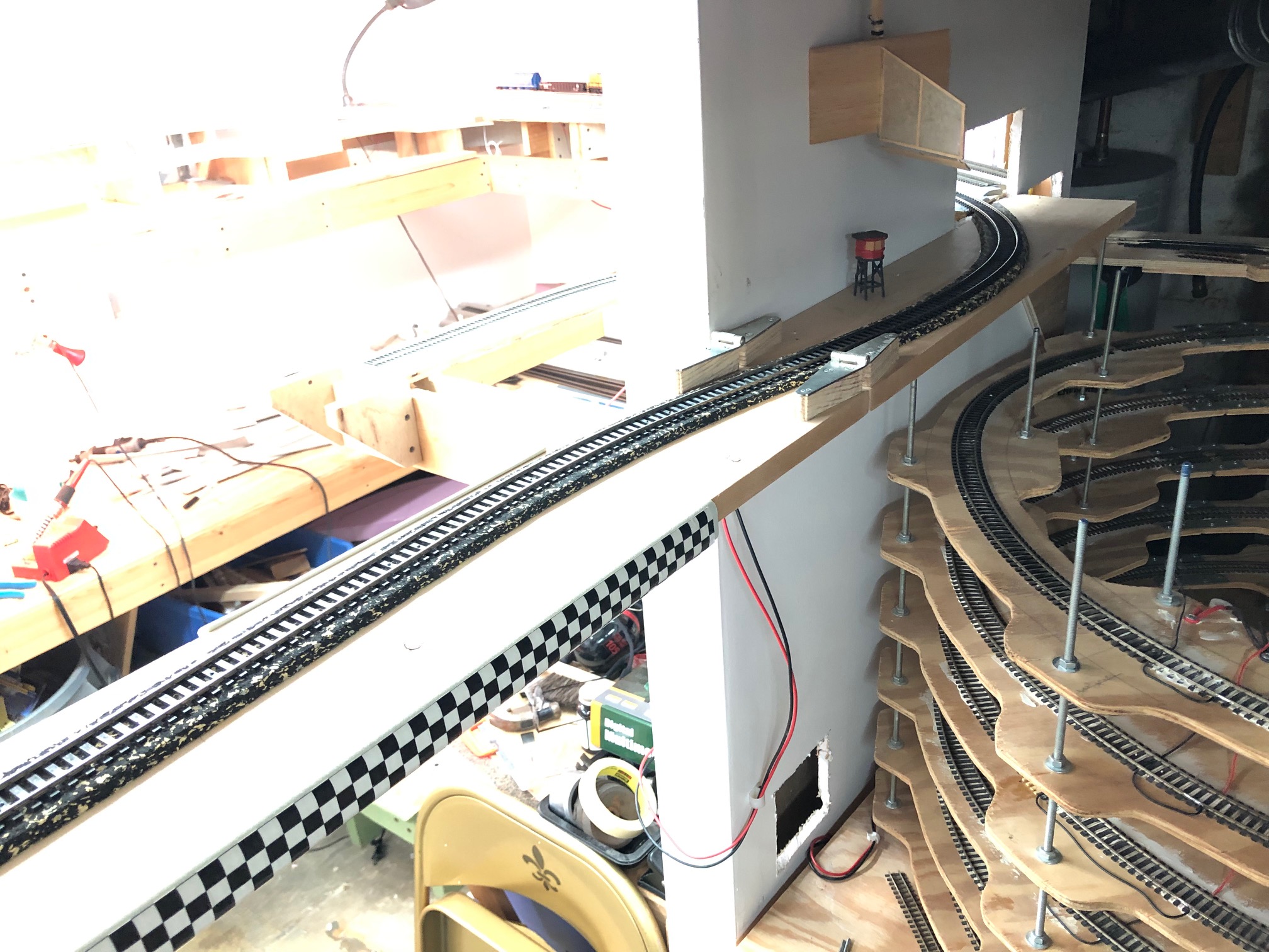
Well, a lot has happened on the layout since my last update, but some of the work would be difficult to spot unless you saw the before & after. Essentially the entire Georgetown Junction (GJ) area has been completely removed and re-worked. I spent some time talking to Matt R. and visiting the Junction area itself with Kelly R. After a lot of discussion and thought, I realized that my original track alignment worked for the model railroad only marginally; my prized Precision Scale B&O Q1c mikado would barely negotiate the curved turnout I had in place. This would not do. Also, I had used two successive Micro Engineering #6 turnouts; one LH and one RH, to create the team tracks and GB main. Not only was this not prototypical but it created a nasty S-curve on the main that looked wonky. I decided that it all needed to come out and the two ME #6’s would be replaced with two Walthers-Shinohara #8 RH turnouts and the curved turnouts would be replaced with wider counterparts. What I didn’t realize is just how much track would have to come up to achieve this goal. ALL of the track from where the staging enters the room down to the Rock Creek trestle had to be removed! All of it! I had to remove road bed (where I could) and reposition it. I had to cut away at glued-down-and-painted roadbed and add more to allow placement of switches. Track feeders were snipped and valleys filled with concrete patch and plaster of Paris. The outcome is that there are more curves and they are much more easy for the trains to navigate. The turnouts the team track yard at GJ is fantastic and looks a lot more prototypical. Downside- the trains switching the yard will have to utilize some of the staging track to perform moves. This is not a huge problem, as the access is not very limiting, but will require folks to move around a bit to get to their train. The good news is that switching the team track yard is not very complex. These were usually used for setting out large cuts of cars and not lots of elaborate moves. Here are some images showing my progress:
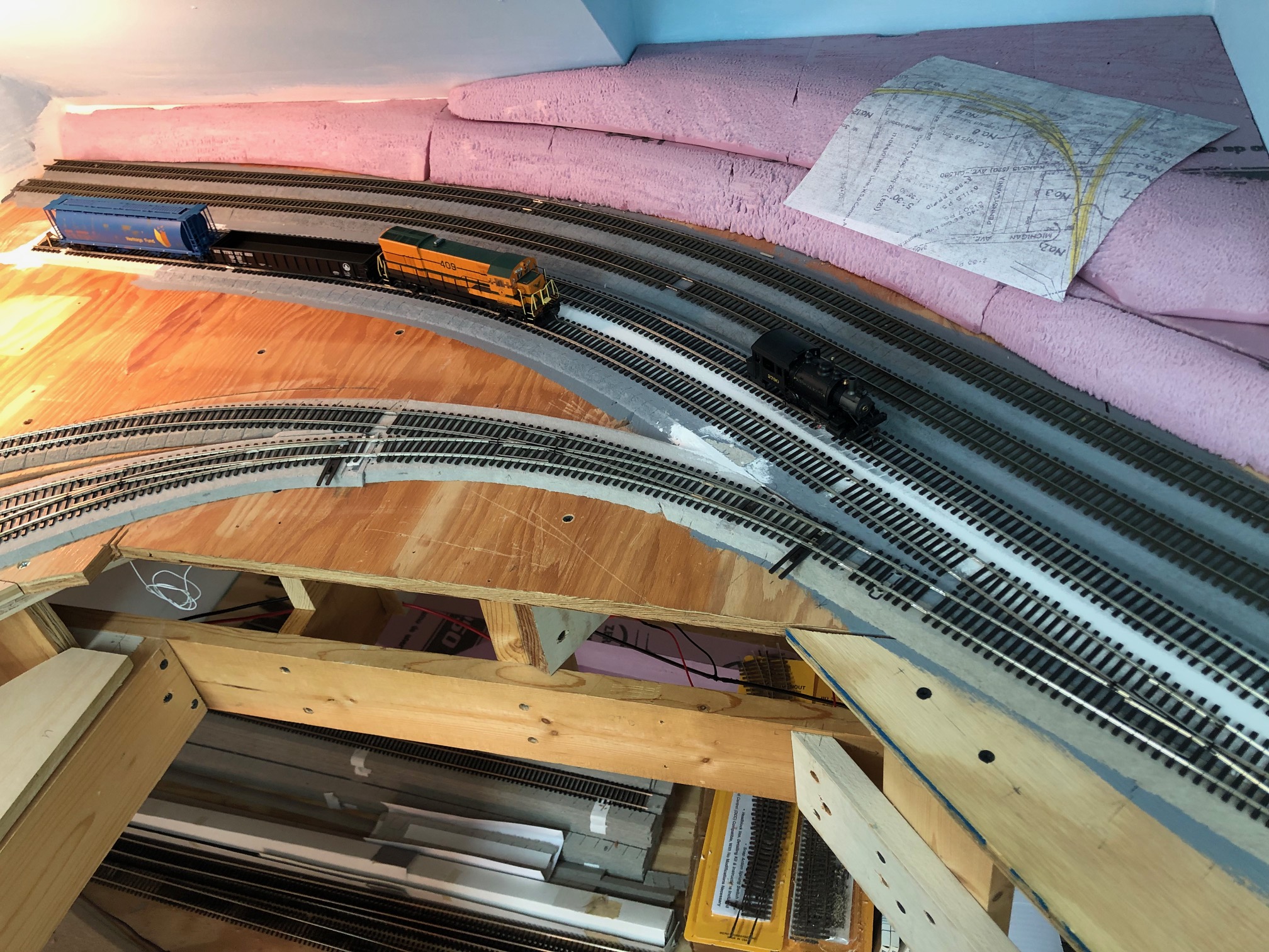
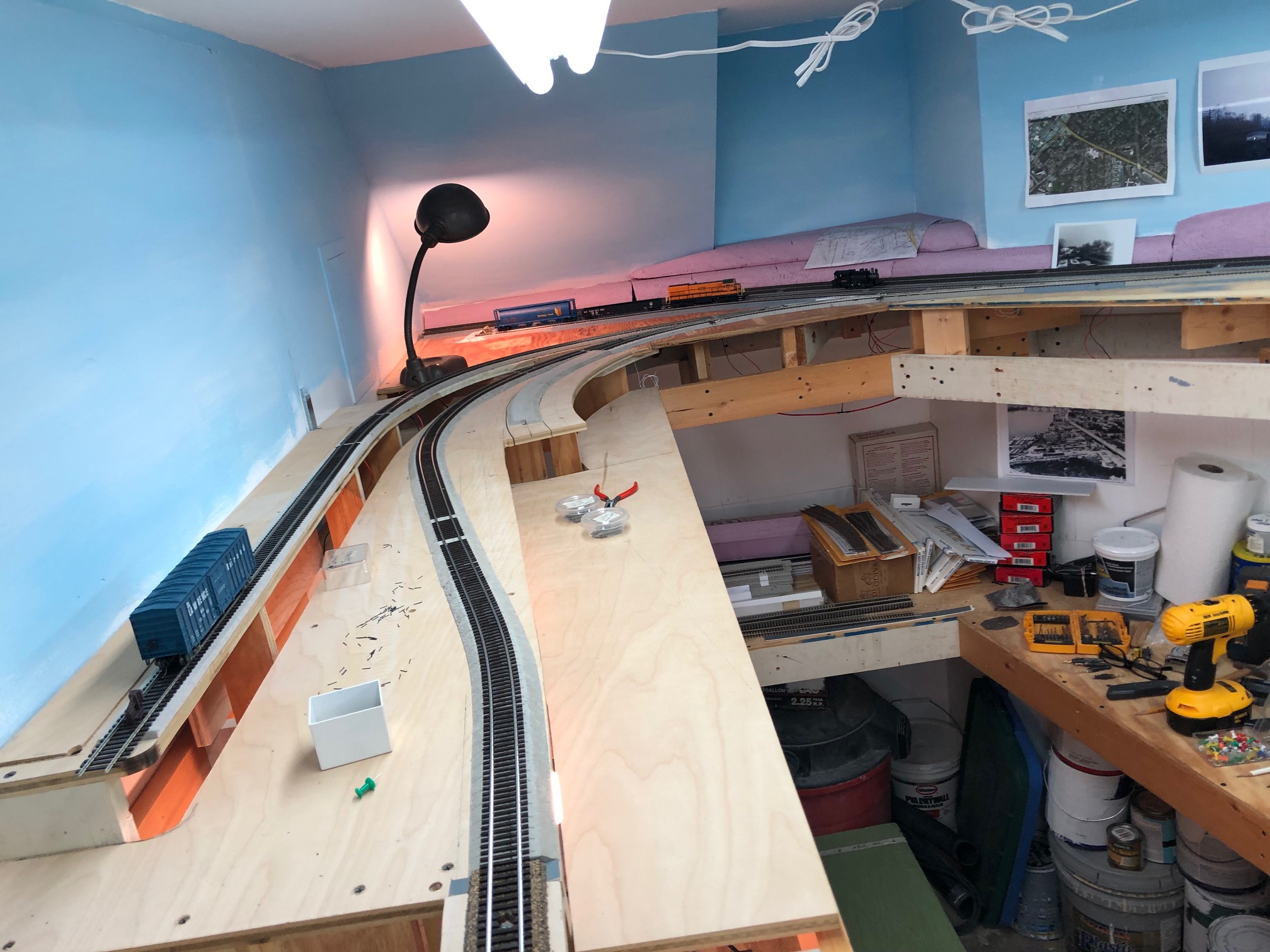
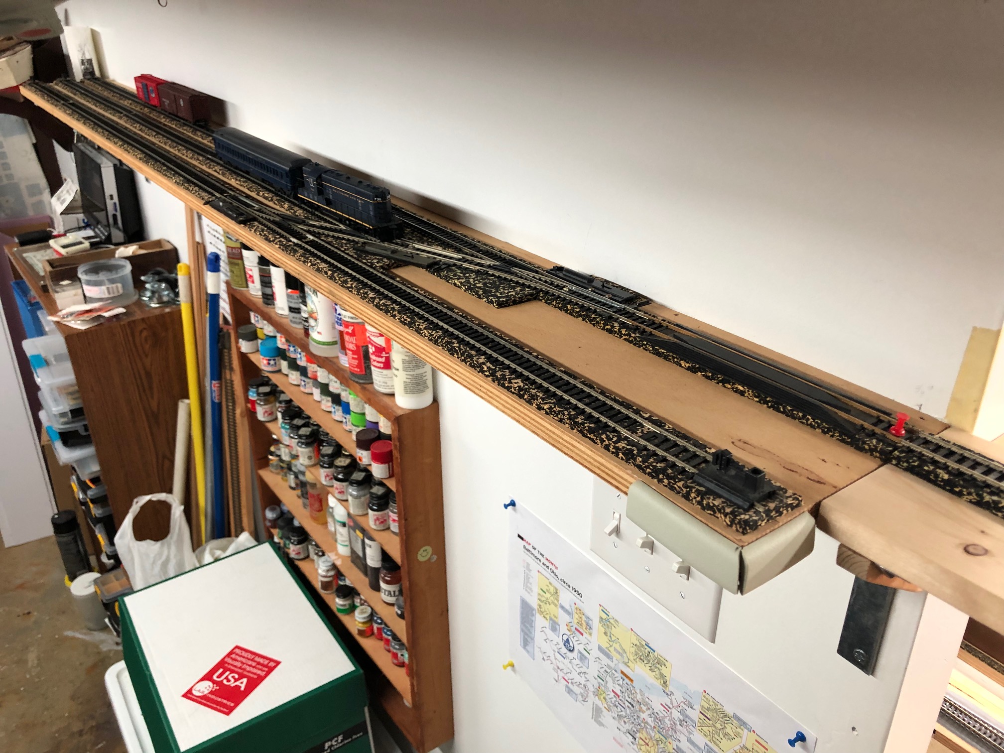
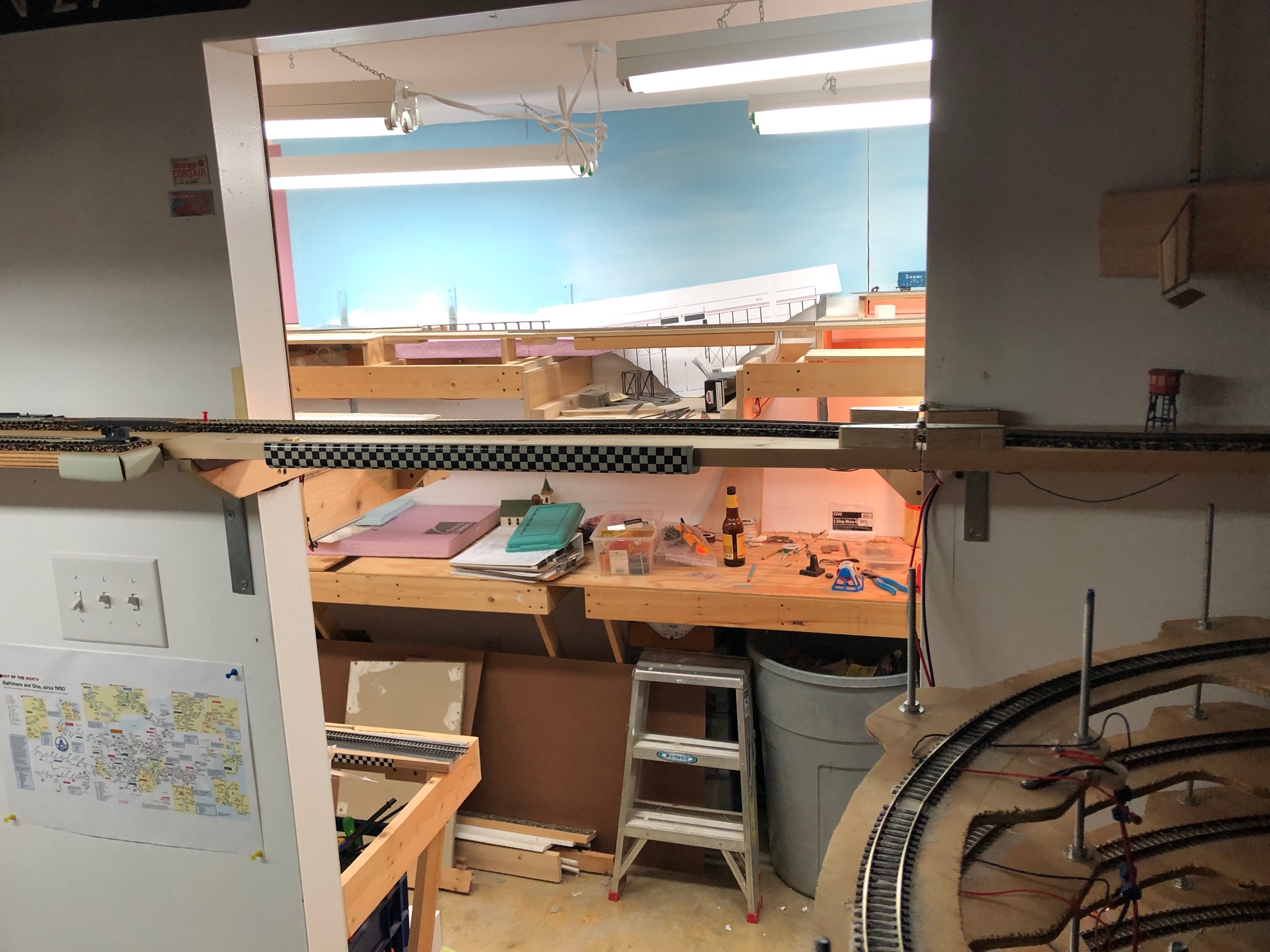
Here you can see how the main and the coal trestle siding have been re-worked at Geo. Jct. All of the switches are being replaced and the alignment is being reworked to be more prototypical and flow better.I am in the process of reworking all of the turnouts and track at the Junction. B&O GP7 703 idles on the passing siding at Chevy Chase.A view of the new turnouts at Geo. Jct. I replaced the #6 LH turnouts with #8 RH turnouts. Reworking the track required removing ALL of the track from the junction down to the trestle and re-positioning and rewiring it. Worth it, though!All of the track here was reworked. I swapped out the curved turnouts for broader ones. I also completely realigned the team track yard turnouts and replaced them with #8’s. Previously, the turnouts were left hand. Now, they more closely follow the prototype and are right handed.All of the track at Geo. Jct. was re-worked over the last couple weeks. Here you can see the west side of the area. Note how the main curves away further to the left to make room for larger radius curved turnouts. This is the Chevy Chase section nearly complete. Track is not completed into the T.W. Perry siding to the right. I will be reconfiguring the team track siding a bit to reduce the curvature. I will also be building a scale model of the Rock Creek trestle to replace the temporary bridge.Here you can see the lead coming off the Junction tracks. This is going to be a functional lead, as trains that are spotting/picking up cars at Geo. Jct. are going to need the space to work.This shelf fiddle yard is my staging yard and future programming track. (the short stub at the bottom is electrically isolated) I will probably upgrade the switch machines to more robust hand throws. The Atlas throws are very flaky.Trains span the doorway on this drop-down bridge. There are rare-earth magnets glued to the board and some lag bolts in the joists above so that the bridge lifts up and stays up when not in use. This is how trains access “Eckington Yard”, which I use for staging.
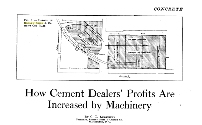
Oct 1921 – Concrete Magazine article on Rosslyn Steel & Cement
While searching for documents, I stumbled on this article from Concrete magazine, published in October 1921 and scanned by Google. The Rosslyn Steel & Cement Co. property has always been of interest to me, as it was served by the B&O in Georgetown. There was a siding that came off the B&O’s Water St. tracks and curved into the RS&C property, past the large concrete cement elevator and into their massive steel fabrication facility. A quite large and long shed housed the steel operation where they produced re-bar and other steel assemblies for use in their construction projects.
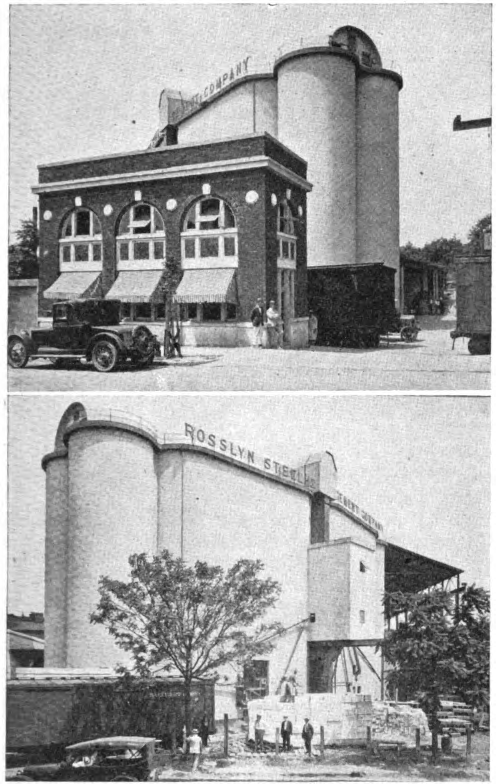
The special thing about this article is that it shows very detailed plans for the RS&C plant and a couple wonderful photographs! They also detail the operations of the cement elevator and the mechanical function of the loaders and unloaders. Really neat stuff! These images and the article text finally give a detailed look at how this plant appeared and was laid out on the site. I’m planning on modeling at least part of it, if I can figure out how to fit it into my layout.
Rosslyn Steel & Cement plant in Georgetown, ca 1921
Happy New Year! I’m catching up on a LOT of updates for this site. I’ve got tons to share and just trying to find the time to get it all online. I had a great work session with Matt R. where we disconnected the DCC system and hooked up a regular power pack to the layout so I could run some of my non-DCC-equipped trains. This served a couple purposes. One, it was cool! Two, it gave me a chance to see how the “biggest” steam engine I have (a B&O Q1c Mikado) did going around the curves of the layout. What did I learn? Well, some of the curves, especially at the Junction are WAY too tight for the Mike. But, I also had some great brainstorming, realizing that I had laid out the track at the Junction in a way that wasn’t prototypical and could be done better to ease the curve and allow for a more prototypical arrangement. I’ve ripped out about 80% of the track I need to remove and am in the process of redoing the roadbed and arranging the tracks. I need to test fit a couple #8 RH turnouts, so that is the next step.
But, the big thing is that I’ve laid track all the way to Bethesda! (yay!) The bad news, I hit a snag. The curve coming into Bethesda is a broad compound curve. On the prototype there were three turnouts. From right to left, a turnout that served Griffith Fuel & Oil and included a long coal trestle. Next is another siding. I’m not certain what this served. The third turnout is the lead for the passing siding, which also led to more sidings serving Maloney Concrete, Frito-Lay and some team tracks among others.
I had originally planned on using some modified Micro Engineering and Walthers #6 turnouts (webbing removed to allow minor “curving” of the turnouts). See here, from last Feb:
But, upon closer inspection, and now that I actually have a lead into Bethesda, I realized these just do not work for me. The #6’s are way too abrupt. The “main” would become the “diverging” route on the turnouts. This looks way too wonky to me. The curve of the #6 is very sharp and it doesn’t flow well, even with bending. I tried some of the broadest curved turnouts that Walthers/Shinohara offers and they are too tight. So what’s left? Are you hearing that? It’s the call of the old-school model railroader… that’s right; Hand laying track!
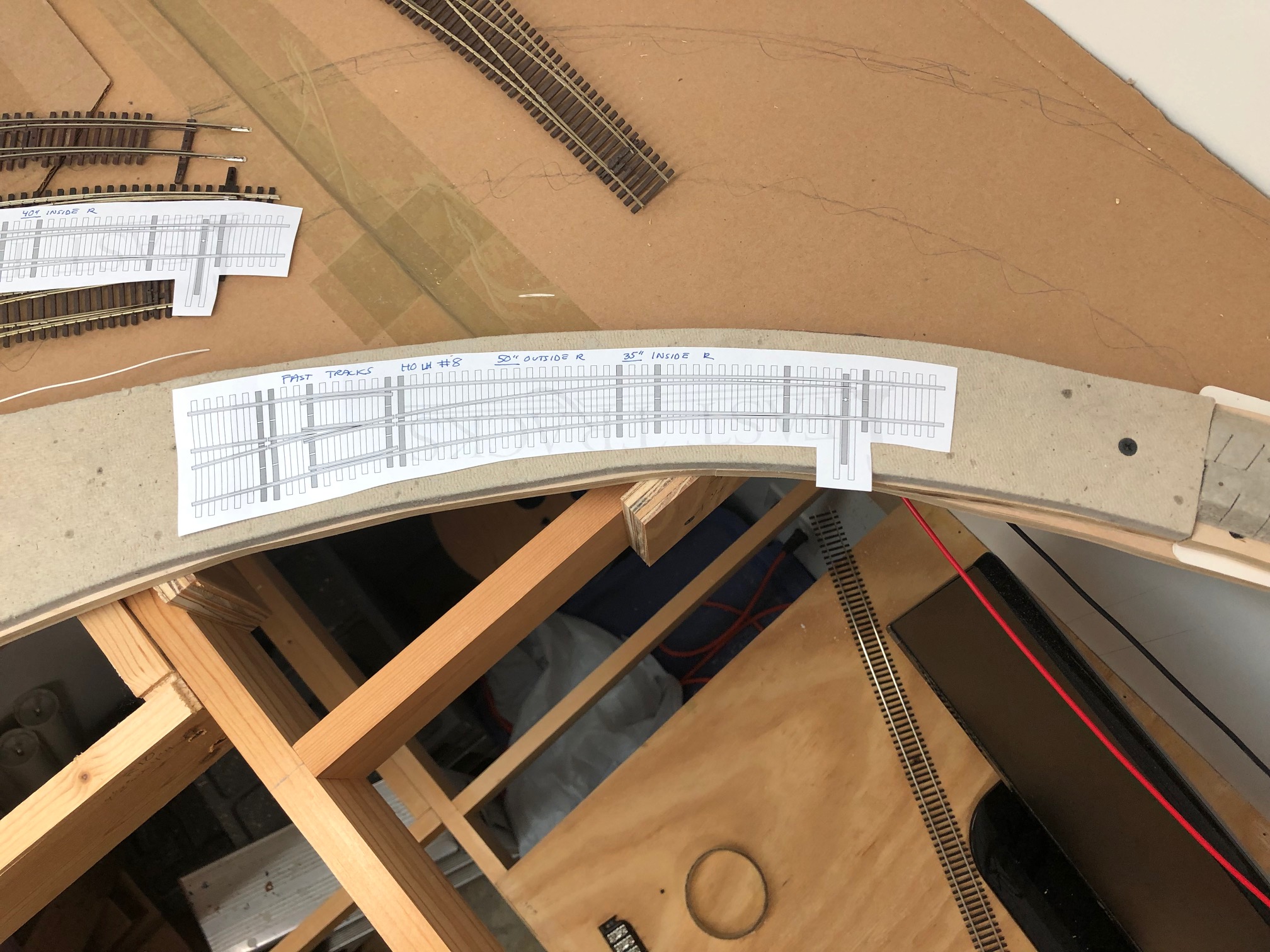
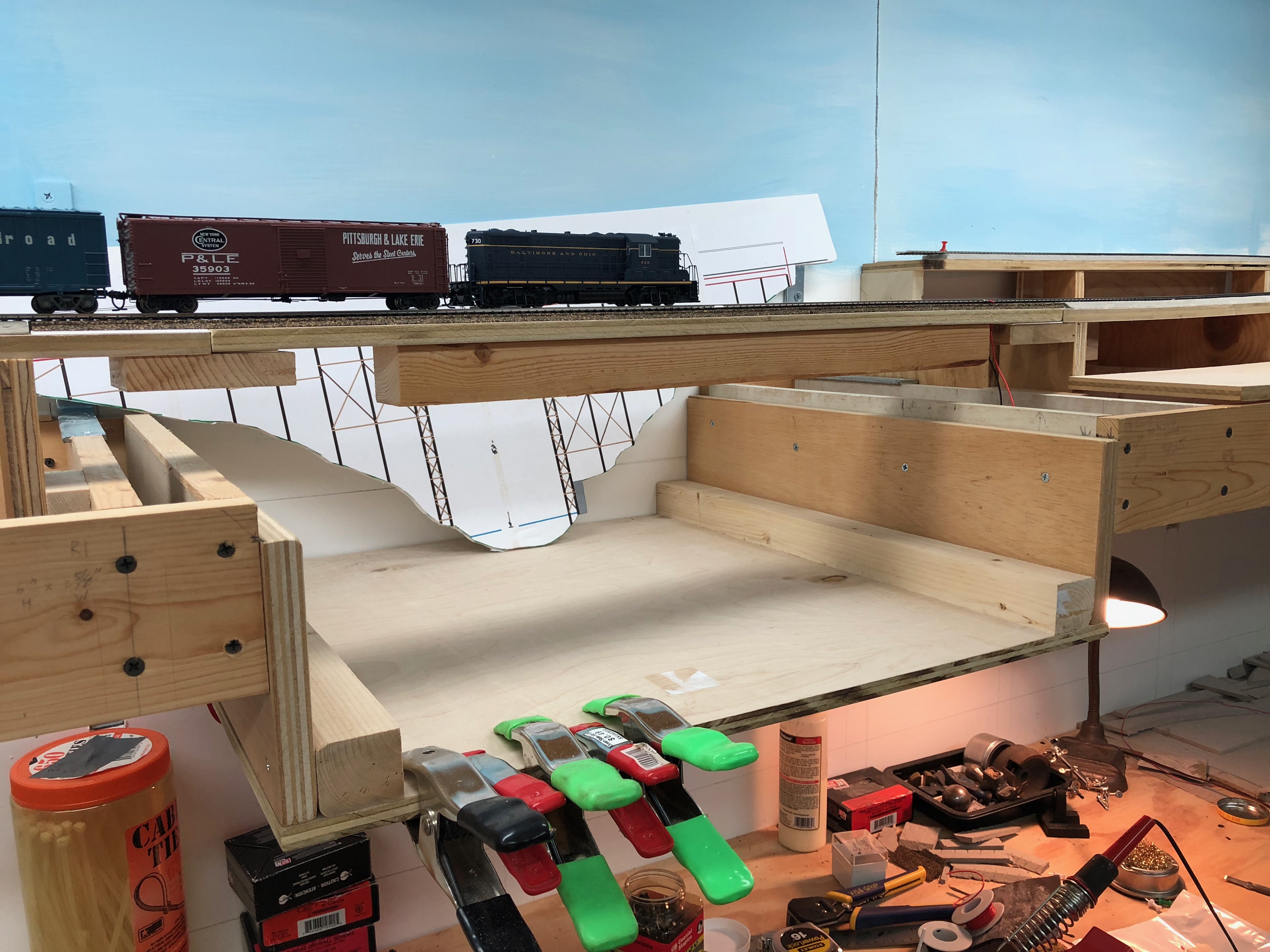
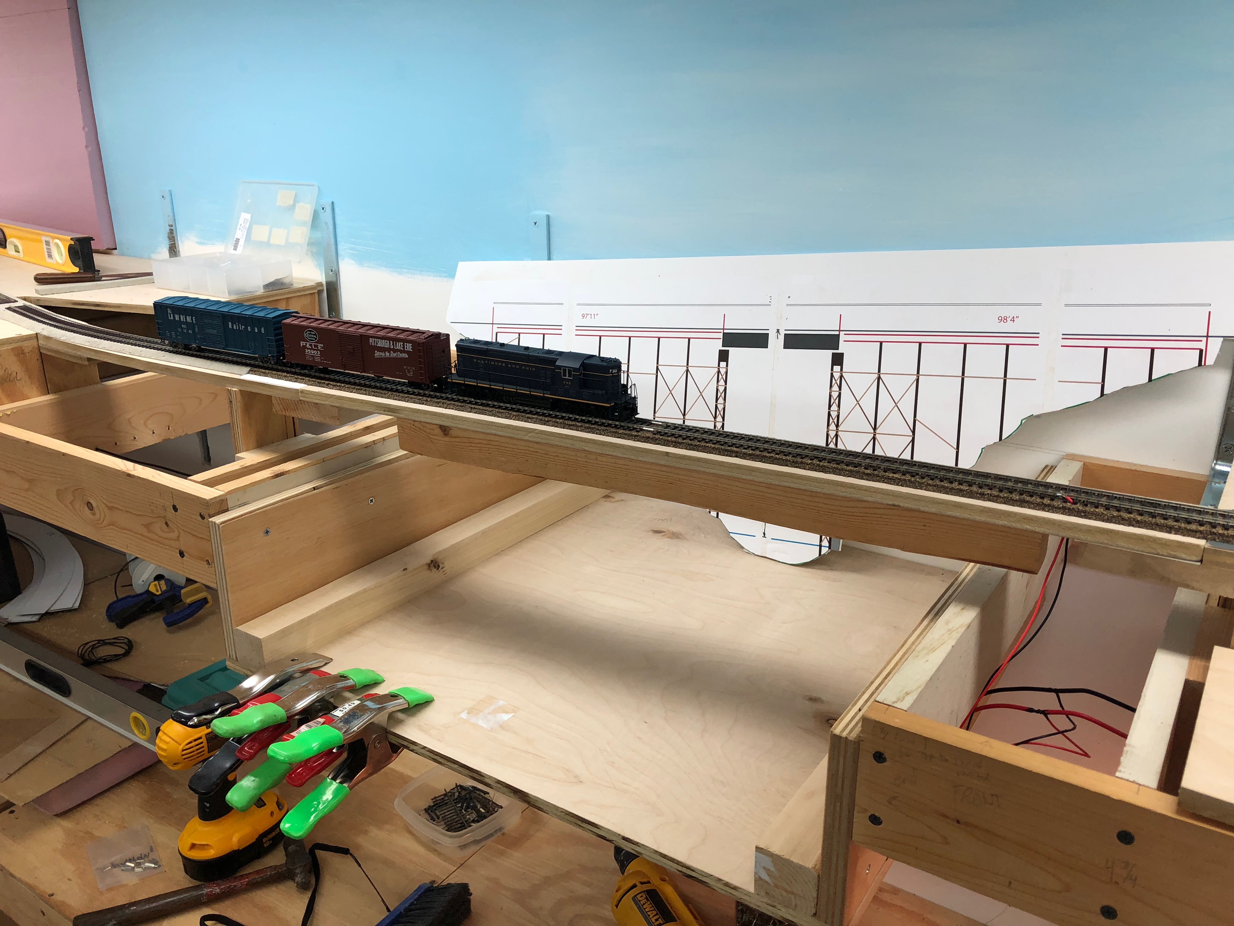
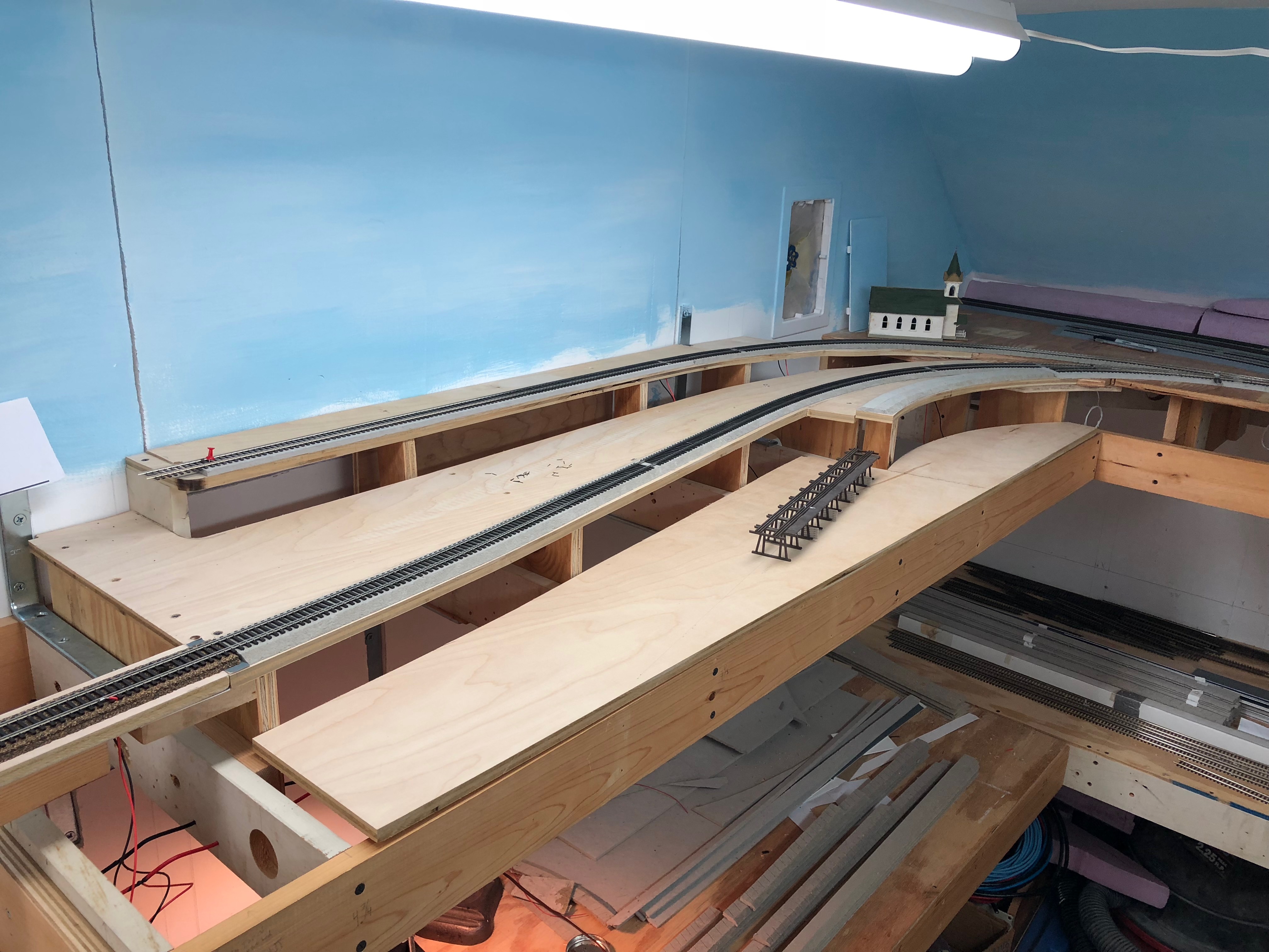
FastTracks is a modern supplier of tools, jigs, and supplies for hand laying track. They have just about anything you could imagine in this realm. I have seen their stuff before and it’s very nice, but also very pricey. I can’t afford to buy a few of the CNC-cut jigs, but I will use their free templates as guides to get my turnouts close to what I need. I printed out about every template that was close to what I am looking for and test-fitted them on the layout. A few of them come close to what I need. Matt and I used a piece of spline to draw a nice curve from the existing track on into Bethesda. This gives me a baseline for the curve of the turnout I need to build. To give you an idea, here is the overall ROUGH arrangement of the tracks in Bethesda:
Next steps: Now that I’ve got the curve drawn on the roadbed, I’m going to cut and remove the roadbed section where the curves are and mount it to a small piece of plywood. This will allow me to take it to the workbench and work there versus on the layout itself. I then need to start test fitting ties and figure out the layout of the turnouts themselves. Alternatively, I may just build three turnouts of the same size and then place them together like sectional track. This will also allow for simplicity, but I won’t be able to achieve the nice compound curve I am following. Either way, I have my work cut out for me this weekend.
As a final note, next weekend (Feb 2-3) will be the Great Scale Model Train Show at Timonium, MD. I will be there and will have some table space to sell some old equipment. If you are going, drop me a line so we can meet up and say hello!
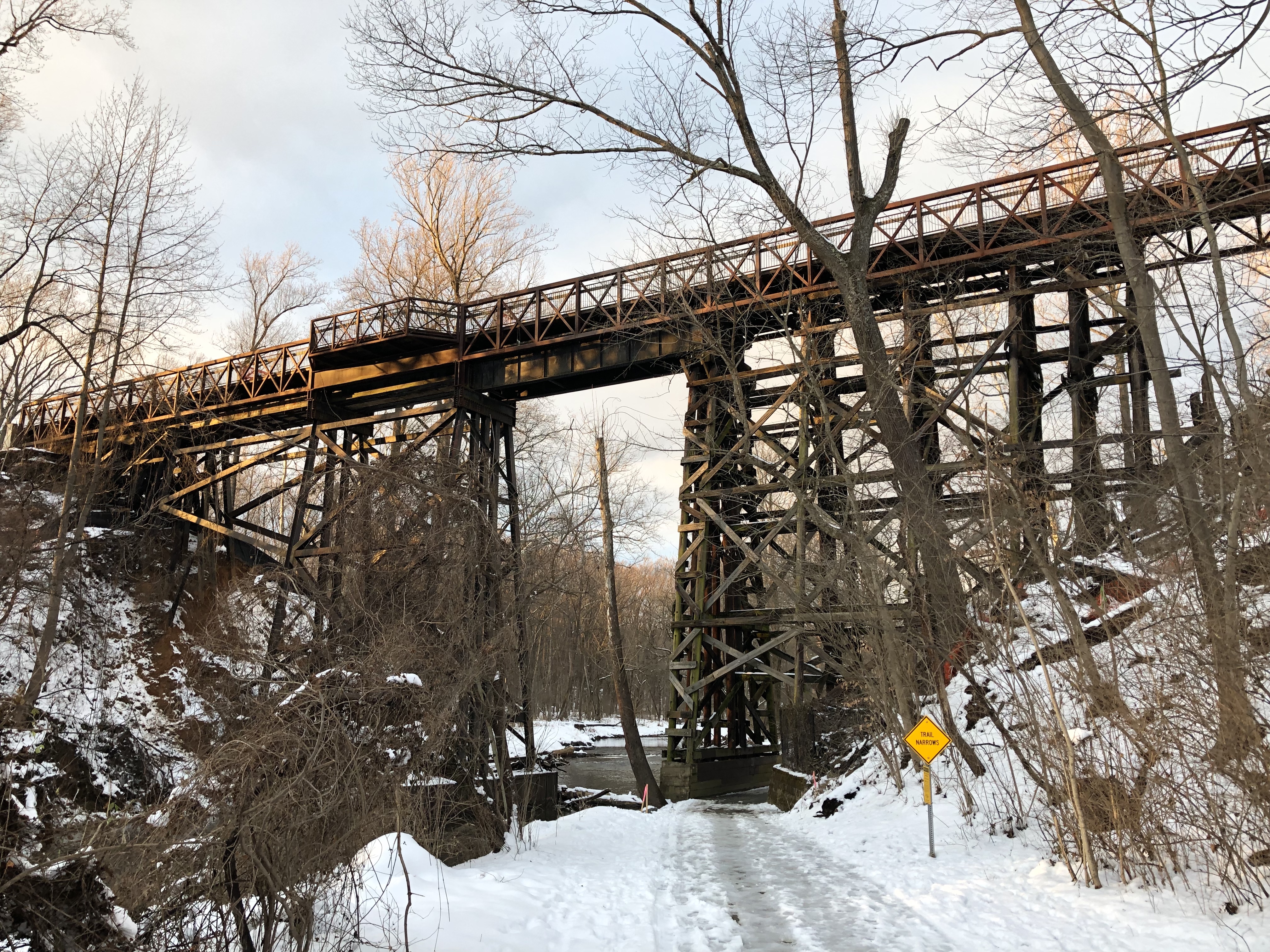
The Rock Creek Trestle, as it stands on January 16, 2019. The trestle is currently in the process of being demolished.
I spent all day Saturday visiting the Georgetown Branch to see some of the construction changes. It was a glorious day. Kelly R. and I found some amazing things. I took hundreds of photos. I’m planning many future blog posts.
The impetus for the journey was that I remembered that the Rock Creek trestle was going to be demolished to make way for a new grade for the purple line. I had no idea if it was already down, but Kelly and I headed over to the site. Much to my joy, it is still partially standing, although about 8 of the trestle bents are gone from the East end.
The venerable structure is not long for this world. Massive mobile cranes are staging nearby to remove the pedestrian path atop the trestle and on the west end, well, the original right of way has been completely decimated. It’s heartbreaking for me to see. This trestle has stood the test of time. Survived fire, flood, hurricane and countless storms and seasons. Since it’s original incarnation as a long wood trestle to what it is today, a bridge has spanned this valley since the early 1890s. It’s a beautiful structure and is showing its age, with rot starting to really take its toll.
I visited today after work to take some final measurements and as many photos as I could snag with the limited sunlight I had. It’s a special bridge for me. Something of wonder. If it’s of any consolation, it will live on in model form on my layout as best as I can manage.
Merry Christmas! Some more great progress has been made. I know it doesn’t look like much but I am making great headway considering the fits and spurts of attention the layout gets. All of the trackage at Chevy Chase is done and wired up. (Minus the turnout frogs, switch machines and the coal trestle at T.W. Perry.) the trains can now run all the way to just before Bethesda. Track is half way through the curve at the end of the room. Feels good to make such progress.
My goal is to get the upper deck done by the end of the year and I’m very close. I have already cut and prepped all of the track in Bethesda but had to rip it up so I could wire frogs and holes for switch machines. I also spent a day working with my friend Matt who helped me add some more prototypical curvature at the east end and rework my sidings. These changes are already in place, I just need to get the track in. One more week? Can he do it? Stay tuned.
Made some great progress this past week. The area around Chevy Chase is taking shape. I laid track halfway through the area and finished fitting the rest of the main and passing siding. I ran out of time to complete laying it. Still need to solder the drops to the rail bottoms and spike into place. After that I will install the team track which will go on the curvy bit of roadbed I installed.
I also installed a new-to-me Digitrax system that was graciously given to me. It’s an Empire Builder 2, about 15 years old but nearly new. Unfortunately the DT300 throttle suffers from the capacitor plague and I will have to have it repaired by Digitrax. Since they were badly hit by hurricane Michael it will not be for a few months. No worries for now, I have an old UT1 to play with. 🙂
Did some cleaning up and consolidating of scenery materials and storage in the layout room and a few other layout tasks. It’s been a productive week! More soon.
Friday view of work completed, showing the roadbed for the T.W. Perry siding (to the right) and the mainline and passing siding (to the Left) laid down as well. Ignore the jumper cables; they were just there to test the track as I hasn’t soldered the feeder wires yet.)
Sunday evening update. The track is laid in for the second half (West end) of the Chevy Chase section. This “boxcar-eye-view” of the track is looking geographic West, with the T.W. Perry siding on the right and the passing siding branching off of the main to the left.
An overview pic from Sunday evening showing the progress. The curved roadbed coming off of the passing siding is the team track. This track is slightly sunken as the prototype was.
Have been really making some great progress on the layout these last few weeks and it feels great. I last updated that I had got my DCC system up and running and after a little tweaking it is working flawlessly. I power up the system, turn the layout power on, open WiThrottle on my phone, acquire a loco and away I go! And on that note…
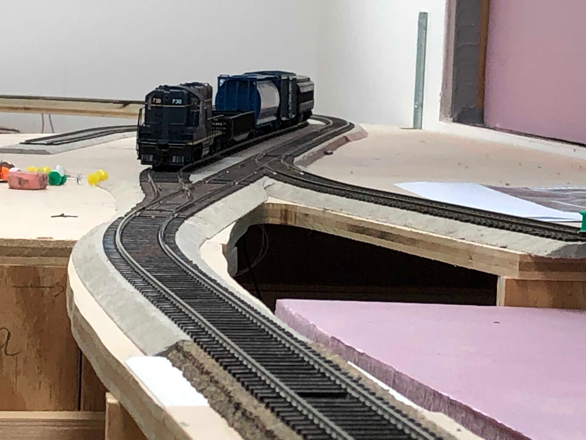
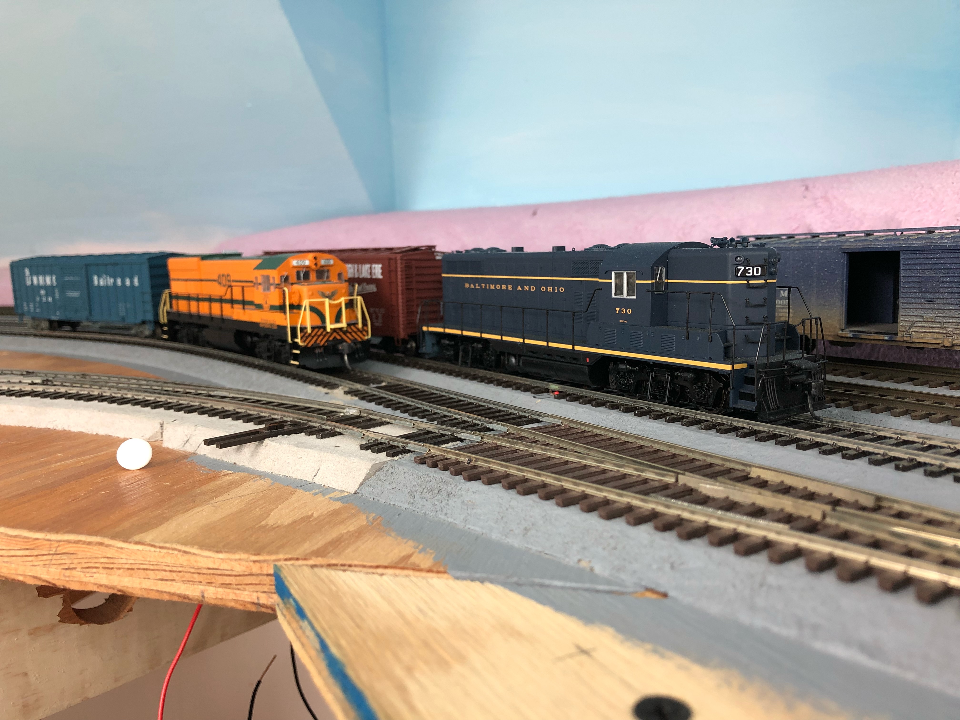
A visiting Maine Central U18B and B&O 730 prepare to switch the Junction.
I’ve completed the Junction area as well as nearly all the trackage in the first section of the layout. Bus wires and feeders are in place and trains are running! There are a few trouble areas that I am working on- the biggest being the sharp curve leading from the Junction on to the branch. Not sure how I’m going to solve this but I’ll work on the major issues when I get closer to them. I can see my steam engines having a hard time negotiating that tight turnout. In the meantime, here’s more…
Here you can see all of the new trackage and lay of the land.
Here you have a nice view of the construction of the lowered section of benchwork. A fully scale representation of the Rock Creek Trestle will go here.
I created the temporary bridge from some plywood with an old 2×2 screwed to the bottom for rigidity. The bridge is easily removable with two wood screws. Feeder wires are screwed into a terminal block for easy removal. Right now track is laid semi-permanently on top of the bridge for operational purposes. Once I have the trestle model complete, I will “cut out” the old bridge and replace it with the model. Since that is far off, the temporary bridge is solid.
The drop down area is where the creek bed will be located. The trestle will be built to scale, an exact representation of the prototype as it stood in the 1940s.
The first train across the temporary bridge over Rock Creek
Just after the junction we have the E.C. Keys siding, the coal trestle and the “main line” of the branch.
In this wide view you can make out the approximate location of the long coal trestle which will branch off from the main right after the junction. I really like how the re-worked grades turned out for the junction area. Originally I had the mainline up very high and it presented some real challenges down grade. My friend Matt helped to re-work the Junction completely. We spent a few hours looking at photos and studying maps to come up with the existing layout, which more realistically follows the prototype, where the Branch drops off quickly from the Metropolitan Branch mainline and is sunken between sidings. (E.C. Keys and the coal trestle) So far, everything is working smoothly. It feels great to make real progress. It feels even better to be able to run a locomotive on the layout! 🙂
Next up I’m going to continue track laying into Chevy Chase and on into Bethesda. If I stay on track, I should make my goal of completing all of the upper-deck track work before Christmas. 🙂