Category Archives: Model RR

Things to do with my model railroad.

Hello, World! (DCC++ & JMRI) * UPDATED 1/2/2022

** UPDATES BELOW **

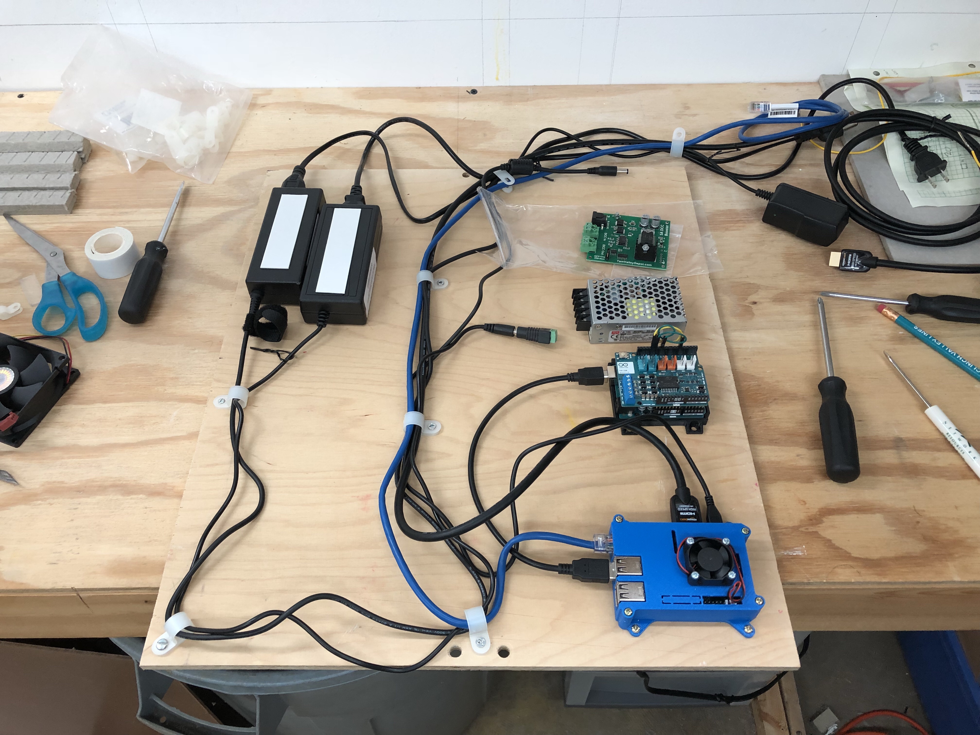
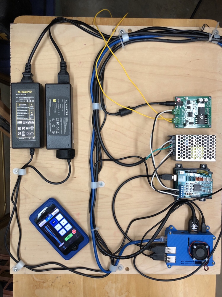
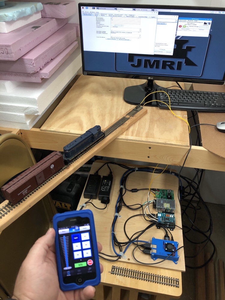
The prototype DCC system is up and running. I decided to home brew my DCC when I read about DCC++ and realized I had an Arduino laying around with no real purpose. I bought a motor shield and hooked up my laptop and an old power pack to test it out. It worked but I knew I had to come up with a more complete and permanent setup.

I immediately considered the Raspberry Pi (RPi) as it’s a low cost, full featured Linux computer and I can run JMRI on it! I needed a power supply and a bit of research found others doing similar things using various inexpensive devices. I also wanted a proper booster so I chose a Tam Valley unit. I’ll invest in a second one for my other power district in the future. EDIT: I used Steve Todd’s “JMRI RaspberryPi as Access Point” which is a pre-built configuration for RPi which sets it up by default as an access point, connects to the DCC++ system and runs PanelPro, etc. It’s fantastic and worked right away.

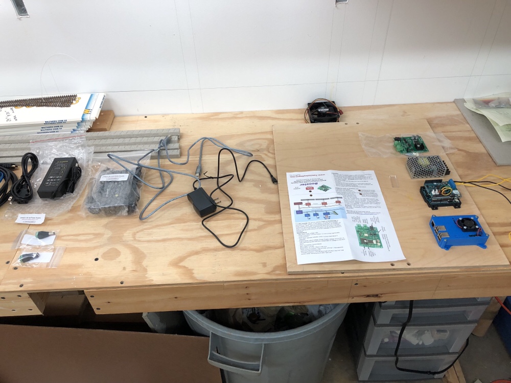
Today I spent several hours putting all the pieces together that I had collected over the last couple years. The monitor was a donor from my dad. The mouse, keyboard and cabling was all old stuff laying around. I put everything onto a board, first laying it out and planning the cable routing. Once everything was good, I screwed the pieces into place.

Next was to test voltages and see what worked. A bit of tinkering and everything looked good. I set it all in place and started configuring things in the RPi. A bit of trial and error getting things to talk to each other, with some luck, and it’s working!

There are still lots of kinks to work out and I need to experiment with a lot of the features. My intention is for this to be a fun project and provide a robust DCC system to get me started for the Georgetown Branch. We will see how it works in the long run.

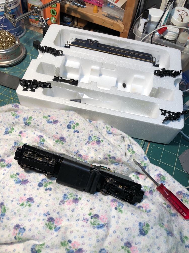
incidentally, I had planned on taking apart my Proto2000 GP7 to have a look at the plastic gears, as last time I ran it it was making lots of noise.

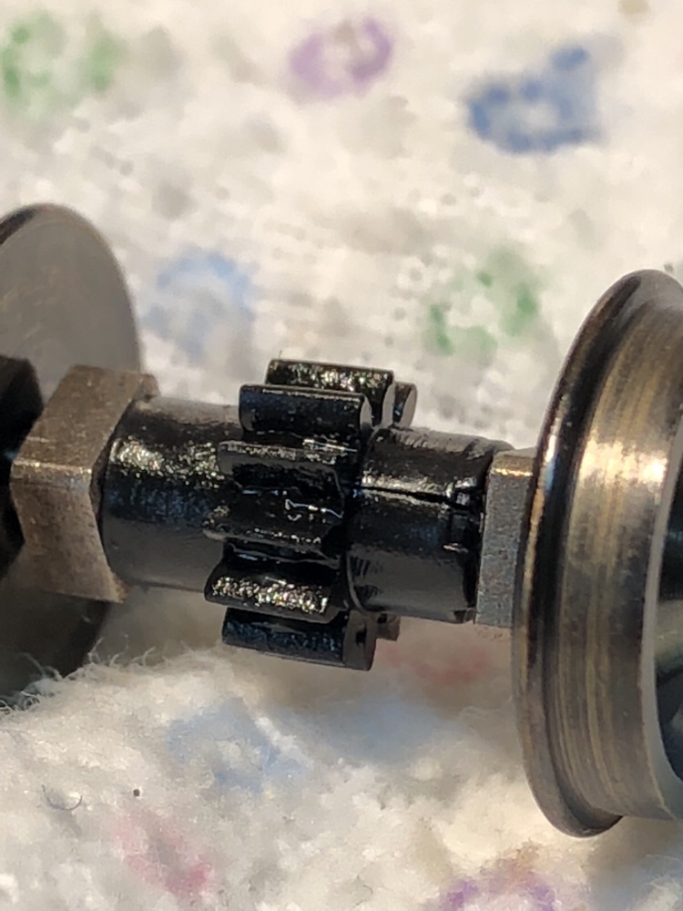
Wouldn’t you know it, all four gears were cracked! I replaced them with Athearn units, like a charm. Here’s one of the cracked units:

I was asked to give some more details about parts and prices so here is a list. Building this setup requires many things that you probably already have on hand, so the cost will vary. Also, you can find things on sale occasionally and you can simplify or streamline it with your own skills or modifications. I included rough estimates for a few things which you will need just to get the ball rolling. Feel free to reach out with any questions you have.

List of parts: (Updated 1/2/2022)

A few more things

Updates: (1/2/2022) – this is not definitive, but rather a couple notes.

DCC++ Issues

I ran into issues with my DCC++ setup, essentially it would read some decoders and not read others. I spent hours troubleshooting it and eventually moved on. I suspect it has to do with my power settings, but as I am not a programmer by nature, I didn’t feel like spending more time figuring it out. I’ve moved on from using DCC++ but would VERY much like to revisit it in the near future as I think there have been some wonderful developments with the growth of the DCC++ EX project; essentially an updated version of the old DCC++ project. They even have a Discord! I have tried DCC++ EX but still have issues. Again, I’d like to revisit this.

Raspberry Pi / Arduino Availablity

I don’t know why Arduino and Raspberry Pi units are so hard to come by right now. I basically couldn’t find ANY for sale right now, anywhere. I’m not sure if this is a result of the global chip shortage, the global shipping crisis, a combination of the two, or something else entirely. If you are in the market for one of these, you’ll have to get creative. It really is a frustrating situation! Let me know if you see things change.

JMRI RaspberryPi as Access Point

Model Railroader and programmer Steve Todd has designed and offers totally free a whole lot of cool stuff on his website. This includes Engine Driver, the awesome Android app you can use to run trains on a WiFi-equipped DCC system! In addition, he offers a completely self-contained, packaged solution for using a Raspberry Pi as an access point to run your layout with JMRI and WiThrottle. Simply write the image to your RPi SD card, boot it up, point it at your DCC system (with WiFi enabled), configure your throttles (smart phones) and you are running trains. It’s amazing. You don’t even “need” a keyboard/mouse to do this. Here is a link to the page with all the info you’ll need: https://mstevetodd.com/rpi I have set this up on my layout and it works great. Really awesome!

That’s all for updates for now. Good luck with your DCC++ adventures. I’d love to hear more about what you all are up to!
The Metropolitan Branch is Complete

Even though it’s a short stretch of track and is purely cosmetic on my layout, it feels great to get it done. The track is some Micro Engineering weathered code 100 flex track that I received in a lot of very old track. It’s probably over 20-some years old, if not older. As such, it required me to drill all of the spike holes, which I did about every 4-5″ with a Dremel. Soldered the joints and pre-bent the curves. This stuff is very stiff and tough to bend smoothly! All in all, it turned out nicely. It will be a great spot to stage a mainline passenger train.

Next is to work on bus wiring, roadbed at the Junction and getting more track down.

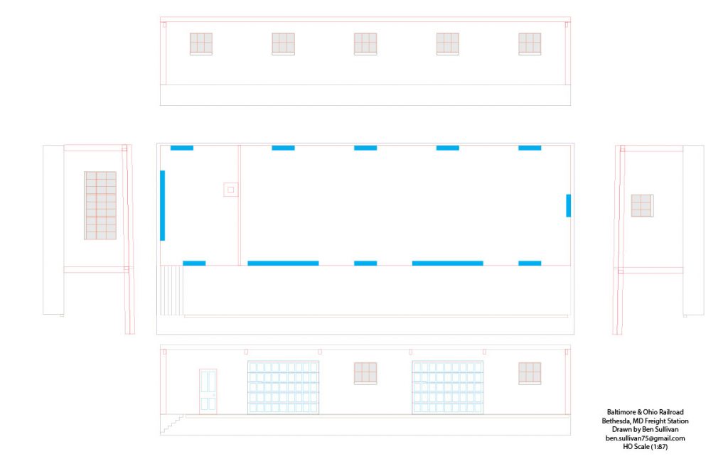
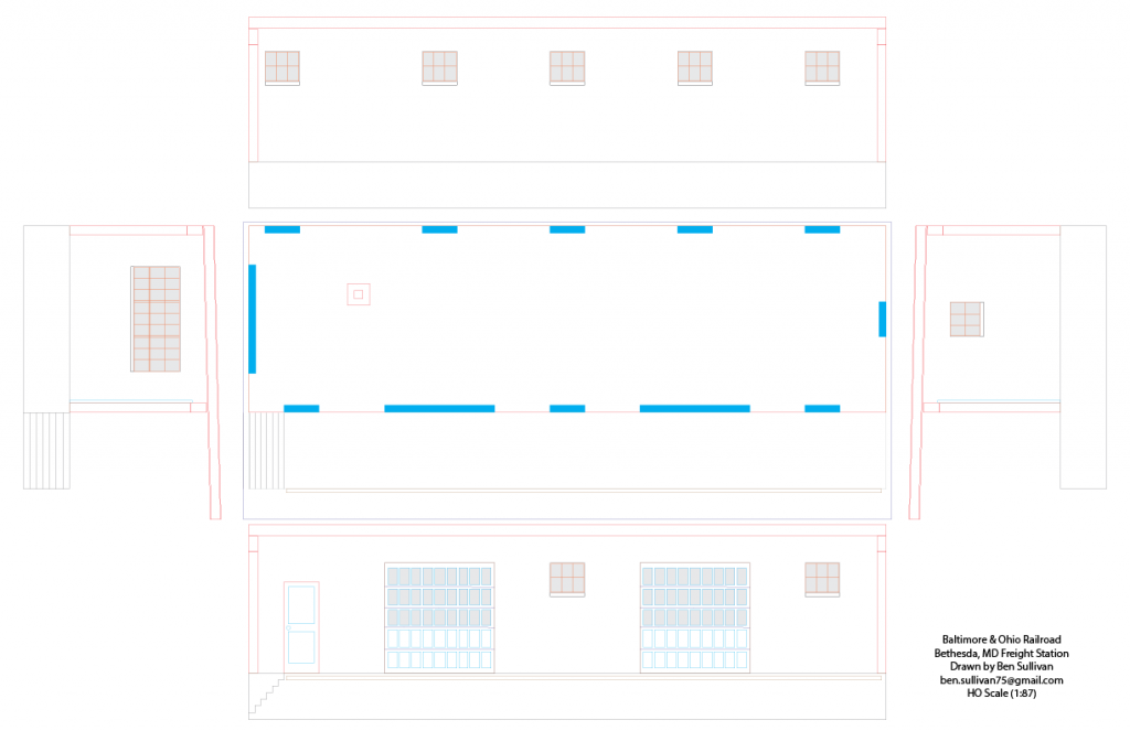
Bethesda Freight Station drawing, v.2

I re-worked my drawing of the Bethesda Freight Station, I’m calling this v.2. I was looking at the first attempt, in laser-cut form, on the layout, and noticed that the loading dock was extremely high. I pulled an HO scale delivery truck up to the dock and it came up about 1/4 of the way up the back door of the truck. Unacceptable.

I went back to my archive photos and the drawings. I reassessed how I got my original measurements and made new references off of the photos, trusting more in some known dimensions I had, namely the garage doors and windows. I also used some logic to determine door size as well as the height of the loading dock. I assumed the loading dock height to be about 42″. I assume the door is about 7′ high. After re-drawing the plans, here is what I’ve come up with:

Here is my second attempt at drawing the Bethesda station after major revisions to the vertical scale.

I’m MUCH more pleased with this result. I know it’s not perfect, but I think it will be about 95% close to correct. I’m going to print this one out, mock it up and see how it looks on the layout. More to come, soon!

Big Layout Update


Progress is coming along nicely on the Georgetown Branch

First up, photos are here. (clicky the link)

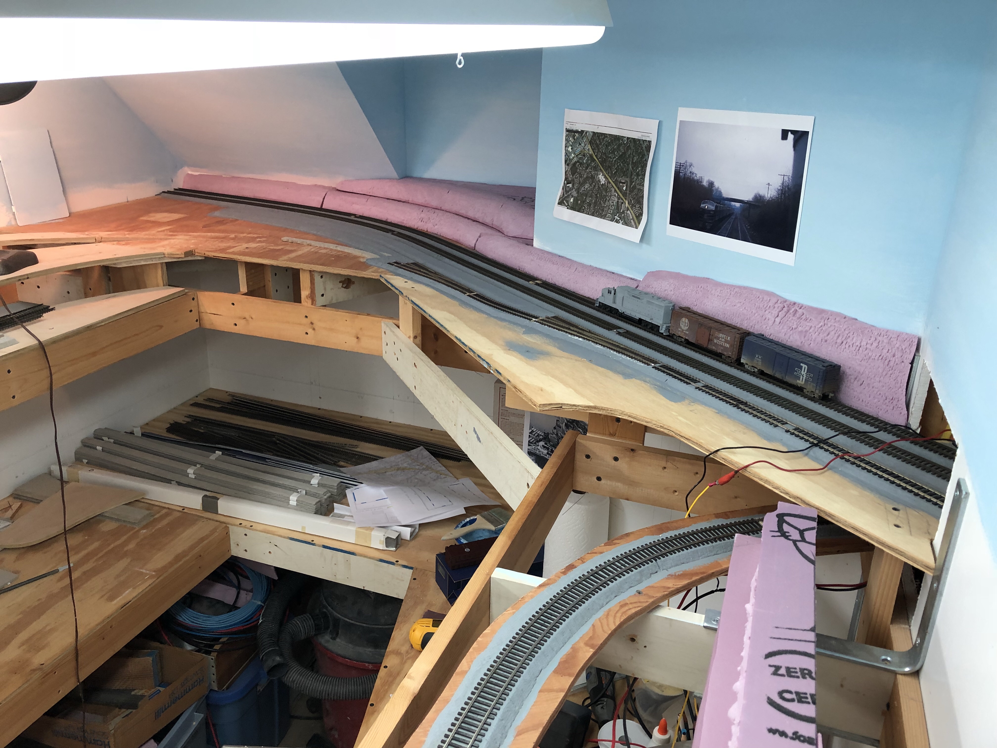
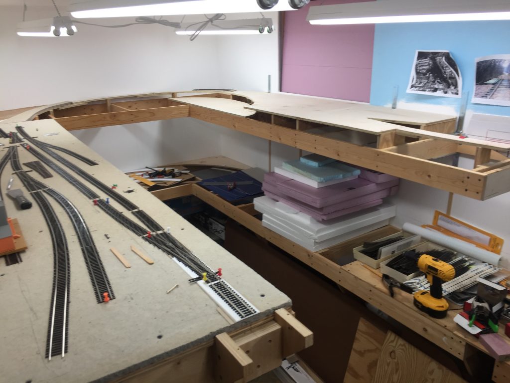
So it’s been a very long time since I did a layout update and a LOT has happened. A year or two ago I reached a point where I really got stuck. When I designed the layout, a lot was left out and as a result I’m having to tackle issues that I hadn’t planned on. You may say that this is a normal aspect of building a layout, and I agree. However, being that I am new at building this type of layout, I really got stuck and discouraged. Between the Summer of 2016 and 2017 I barely set foot in the basement. I spent maybe 2 or 3 days of work over the entire time span. Why? I couldn’t figure out the track arrangement between Georgetown Junction and Chevy Chase. I had mistakenly ignored elevation and as such the design was asking for the track to go down hill about 6″ in about 10 feet. The grade was ridiculous and I tried many methods or alleviating it. None worked.

During that time, I made friends with the son of a late member of my model RR club. He and I had met before, but never really spent time talking trains or what projects we were working on. Turns out, he’s building a tremendous layout in his basement that is an absolute gem. (I hope to profile it some day!) He and I have been working on each other’s layouts over the last several months and I couldn’t be more happy on what progress is being made. More progress has been made in the last few months than in the last few YEARS! It’s really fantastic. He helped me figure out the grade issue, taught me about good wiring techniques, really seeking the soul of the prototype to dictate how the track plan is refined and implemented, good practices, the magic of plywood sub roadbed (I was planning on using splines) and how to make track mockups out of cardboard. All of this (and so much more) has put me on a fast track to getting a LOT done. I’m going to share some photos here, and plan on doing more in the near future. I am considering doing a vlog, but that remains to be seen, if I can find the time.

More updates soon, I hope!

Bethesda Freight Station Mock-Up

I told you fun stuff was happening! So I had a chance to test out my drawings and laser cut the station out of mat board as a proof of concept. Wow! I am so pleased. The drawings proved to work perfectly well. Have a look:

Next steps: I need to finish the drawings. I am now applying textures (brick, concrete) to the file so that when I do my actual laser cutting/engraving all of the bricks are represented as well as the concrete foundation. I even sourced images of brick which match the pattern of 5 and 1 for the soldier courses. I also sourced some .020″ laserboard which I will use to create the custom windows and garage doors. I didn’t realize that the top three courses on the garage doors were filled in with glass panels!

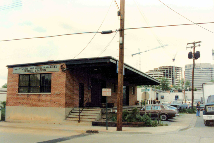
And for reference, here is the station in 1984:

5/16/1984 Bethesda Freight House. Photo by Matthew Vurek.

More to come soon. Stay tuned!

Bethesda Freight House – Fun Things Are Happening

A drawing I created from blueprints and photos to recreate the Bethesda Freight House in HO Scale.

Progress is being made on my HO Scale model of the B&O’s Bethesda, MD freight house. This unusual structure consisted of a rectangular building build of concrete & brick with a loading dock and two garage doors. The oddest thing about the structure is the fact that it was never connected to (nor aligned with) any railroad tracks! I believe it was never intended to handle much more than administrative capacities and smaller LCL freight items, perhaps. More details on the build soon!

Model Railroad Planning – Fitting the Bridges Over the C&O Canal

I’ve been on a hot streak lately working on the layout and have made tremendous progress thanks to help from friends. I hope to make a blog post soon detailing the progress and maybe a vlog. For now, I’m spending time thinking about designing and building the three bridges that carried the B&O over Canal Rd. and the C&O Canal down in DC.

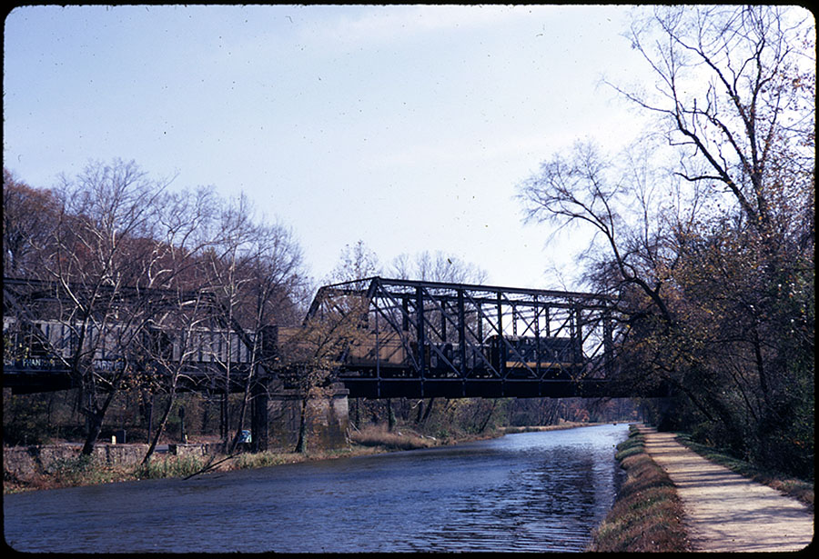
B&O H12-44 9725 leads the Georgetown Local westbound across the C&O Canal toward Georgetown. Wm. Duvall photo (ca. Nov 1966)

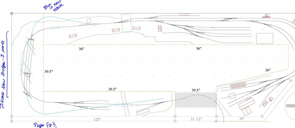
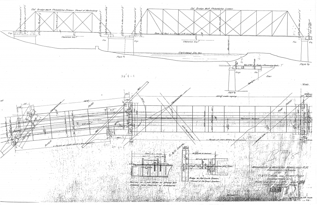
This is the spot where the line had nearly descended all the way to the canal level and broke away from the Palisades and crossed over toward the Potomac River on a beautiful trio of historic bridges and sweeping curve. I have the blueprints for these bridges and plan on modeling them, but I need them to fit my space. Right now it’s a very tight fit. I did a mock-up below:

Mocking up the three bridges that carried the B&O across Canal Rd. and the C&O Canal. The *just* fit!

I’m considering options for including the bridges. Everything from only modeling one of the three, two of the three, or all three. Curving them more. Using tighter radius curves at the approaches. Or moving it to another location. One final option is to ditch it altogether. What do you think? Feedback below!

Modeling Link: Scratch Building a Whipple Truss Bridge

B&O Bridges over the C&O Canal

I found this link ages ago but wanted to list it here in case anyone is curious. This gentleman, Craig Bisgeier, has a New England model RR set in 1892. On his layout he needed a Whipple Truss bridge so he set out to kitbash/scratchbuild one from two Central Valley 150′ Pratt Through Truss bridge kits. The build is pretty involved and detailed. I wish there were more photos but nonetheless it’s a great resource for a modeler like me who is considering this daunting task! One benefit I do have is a full set of blueprints of the bridges crossing the canal. My plan is to laser-cut custom pieces as needed from thin mat board. More on this in the future.

http://housatonicrr.com/Whipple.htm

A Photo Surprise – Lumber Straddle Carrier in Bethesda

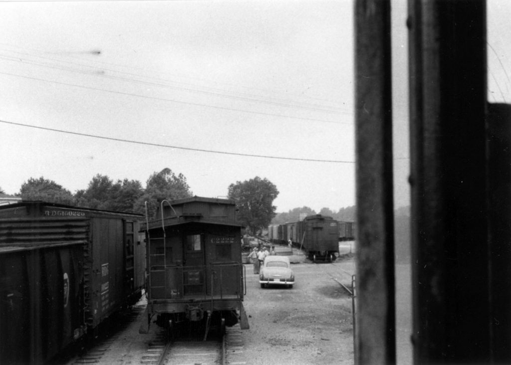
Last weekend, while doing some research on track and industry layout in Bethesda with my friend Matt I was looking at a photo that I have looked at many, many times before and noticed something completely new and exciting. (don’t you love it when that happens?!) Here is the photo:

May 30, 1956. B&O C2222 and full yard at Bethesda. Ray Mumford photo.

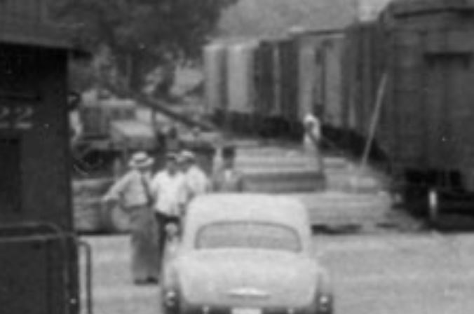
Looks pretty normal. A really full yard at Bethesda. The road crew, on an S2, a short distance from C2222, the “local” caboose that ran regularly on that assignment. In the background is Bethesda Avenue, with a car parked next to it, a few gentleman talking and some freight unloading going on in the background. Well, here’s the fun part. “Computer. Zoom and enhance!” (I love saying that.)

Close up view of the freight unloading.

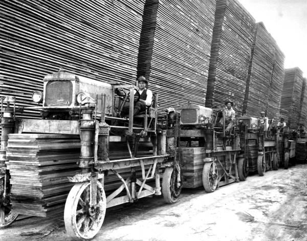
Immediately my brain triggered. “Hey! I know what that thing is! Look, do you see it?!” I exclaimed to my friend Matt, sitting next to me, looking befuddled. It’s a straddle carrier. A lumber straddle carrier. These neat vehicles were invented around 1913 and had four wheels which could turn independent of the others, allowing the vehicle to maneuver in tight spaces. The bottom is open and has arms which can grab a stack of lumber beneath it. Really brilliant. They were common in lumber yards around the country until the advent of the fork lift and palletized lumber. In some instances these vehicles are still used today and are even produced for specialized applications by some of the manufacturers who made them back then.

Hauling lumber with straddle carriers at Putnam Lumber Company - Shamrock, Florida. 1929. Black & white photoprint, 8 x 10 in. State Archives of Florida, Florida Memory. <https://www.floridamemory.com/items/show/24975>, accessed 12 January 2018.
Hauling lumber with straddle carriers at Putnam Lumber Company – Shamrock, Florida. 1929. Black & white photoprint, 8 x 10 in. State Archives of Florida, Florida Memory. <https://www.floridamemory.com/items/show/24975>, accessed 12 January 2018.

So why is this special?

Well, it’s another fine detail that brings the setting to life. Had I never zoomed in and noticed that tiny detail, I would have never known there was one in Bethesda. It means that in my modeling of the area I can include this distinctive vehicle and it will be prototypical. I love these things. They’re quirky and eye-catching. I have no other photos that I know of showing the straddle carrier in Bethesda, so it is rather special.

How was it used?

Well, I doubt it was used by the Einsinger Mill & Lumber Co, as they had their own siding into their yard. It very well COULD have been theirs, but there were several other lumber yards in the area (Devlin, for example) who may have used the straddle carrier to shuttle lumber to their yard just a short distance from the team tracks in Bethesda. You can see a gentleman stacking lumber to the right. The lumber would be delivered by boxcar as was common at the time. The lumber would be stacked and then the straddle carrier would drive atop the bundle, grasp it and then shuttle it to the yard for storage and sale.

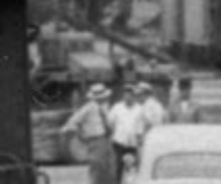
Closeup of Lumber Carrier

I NEED YOUR HELP!

I want to identify the make of this carrier. I have been hunting high and low for a photo or reference to the specific unit pictured in this image. Look carefully at the engine cowl, the wheels, what appears to be shrouding over the front wheel mounts up top, the rear gear assembly/cover and front opening. Also, don’t be fooled by the silhouettes of the gentlemen in the foreground, especially the one to the right. Try to crop those out. Also note what appears to be a gas tank of some sort just behind the carrier. Is this part of the unit? I can’t tell. Distance-wise, remember this this is REALLY far from the photographer in the photo. The distances are really squished together at this distance. If you have any info that could help me, please email me at cpl_clegg at yahoo dot com.

Final Note

These kind of details revealing themselves are the things that keep me hunting for more and more photos, stories, maps and documents related to the Branch. It intrigues me and I enjoy it tremendously! One other thing I noticed, further back, beyond the straddle carrier there appears to be a bulk transfer conveyor loader. These were seen in just about every town and it’s no surprise there was one in Bethesda. One end of the conveyor would be placed beneath a hopper and a truck would be spotted at the upper end. Once turned on, the hopper would be opened and the contents loaded into the back of the truck. Think sand, gravel, etc.

Lone Star Cement Sign

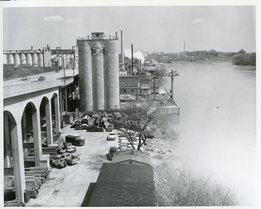
Lone Star Cement plant in Georgetown, DC on the waterfront. Date unknown, most likely early 1960s. Photo from DC DoT Archives. (https://ddotlibrary.omeka.net)

As I prepare to model various structures along the Georgetown Branch, my attention turns to recreating various details such as signs, vehicles and small details which establish the scene in historical context. Of course I have to pick and choose these details because I don’t have room to model the entire branch line.

One of the structures I plan on modeling is the Lone Star Cement plant. This large structure sat at the west end of the industrial waterfront in Georgetown. The silos towered above the Whitehurst Freeway and were emblazoned with a very large Lone Star logo. Using some photos and Adobe Illustrator I re-drew the logo as best I could, to be a relatively decent representation of the one painted on the silos of the plant. Here is a JPG of my attempt.

Lone Star Portland Cement Georgetown sign
The Lone Star Cement sign, re-drawn by me.