Here are a few snapshots from a 1959 Baist map from Ryan S. Thank you, Ryan!

Here are a few snapshots from a 1959 Baist map from Ryan S. Thank you, Ryan!
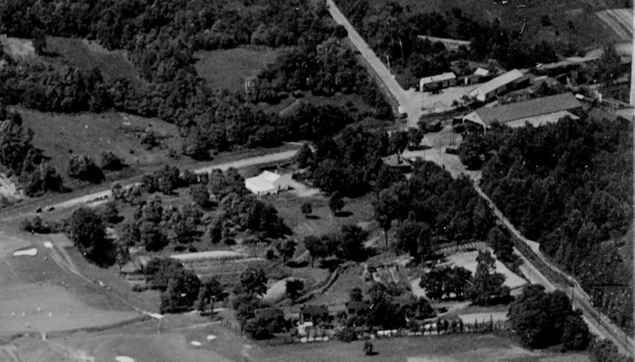
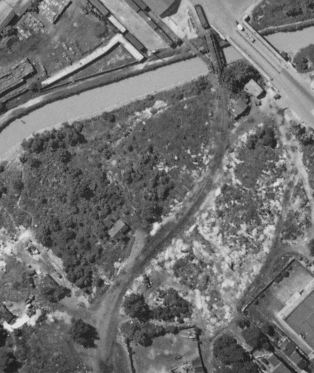
Another absolute gem from the National Archives is this aerial view of the Columbia Country Club, which the Georgetown Branch bisected. Visible in the upper-right corner is where the GB crossed Connecticut Ave and served a few industries including T.W. Perry and the Capitol Traction powerhouse, barely visible on the far right edge. It is interesting to see how T.W. Perry was configured at this time; the lumber shed is visible as is the coal trestle behind it. The large Capitol Traction car barn and Rock Creek Ry. station are both visible as well. Not yet built is the large water tower which sat next to the car barn and the well-known Chevy Chase Lake swimming pool. This was only 11 years after the line had been extended from this point down Georgetown. Chevy Chase Lake was the terminus of the branch from ca 1892 until 1910.
I have oft wondered what methods the folks at Wilkins Rogers Milling used over the years to offload/load grain and other materials at their mill. I have seen photos showing boxcars but never covered hoppers, until now. Most of the time there are various boxcars sitting at the loading dock. Some showing grain doors indicating bulk loadings and others without, indicating bagged loadings. Both are reasonable. But I’d never seen a covered hopper of any kind there in the older photos I have, which is not too many good ones.
Perusing the DDoT DC archives page (which is great!) I stumbled on some photos from the flooding in Georgetown during Hurricane Agnes in late June, 1972. In one image, showing the mill, sitting on the siding at Wilkins Rogers are four cars; three boxcars (one, oddly enough, from the UP, apparently!) and one cylindrical covered hopper!
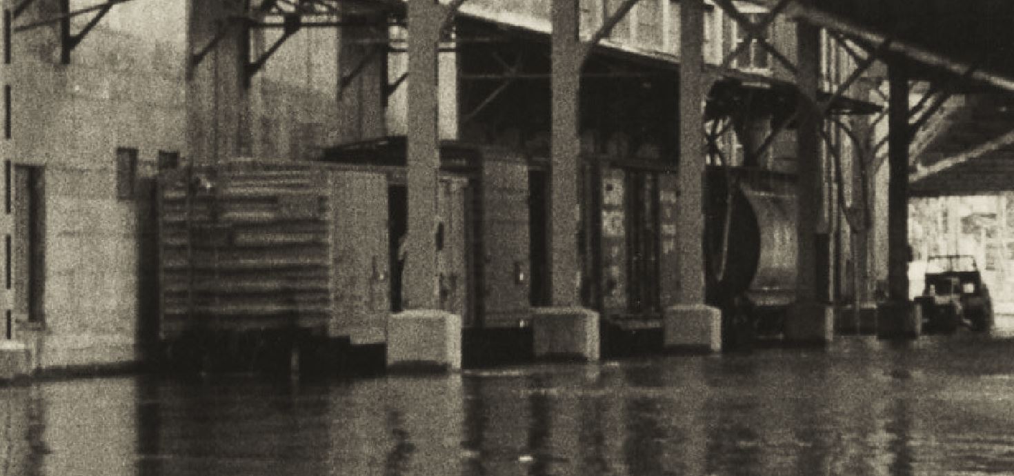
I can’t make out any reporting marks and I’m not an expert on these sorts of cars, but it seems there is an air hose connected to one end, draped up to a valve, most likely, which would be assisting in the unloading of whatever grain was inside. *EDIT- Matt R. says: Probably an ACF 3500 CuFt covered hopper. Atlas makes the model. Dates to early 60’s. Many different owners as well as ACF’s own lease fleet.
General American developed the “Airslide” covered hopper, which used air and a special membrane to move materials out of the car chutes with ease. These types of cars are new for me, as I haven’t really studied them. A quick search turned up a site with some great history and back story on these cars. As it seems they started showing up in 1954, I can include them on my layout, which really is delightful. It seems that Con-Cor produced a model of this car, which is close to what I would use. More research is in order.
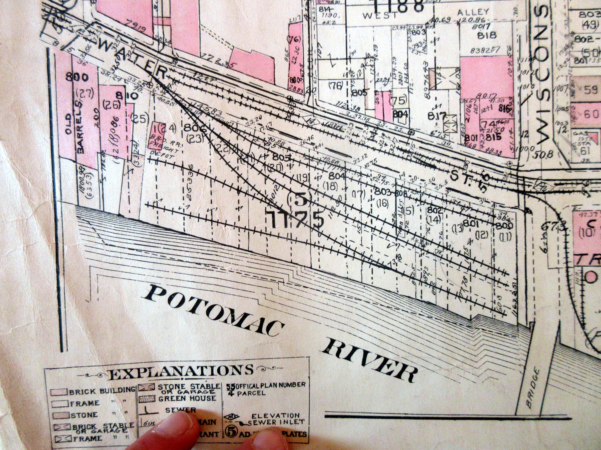
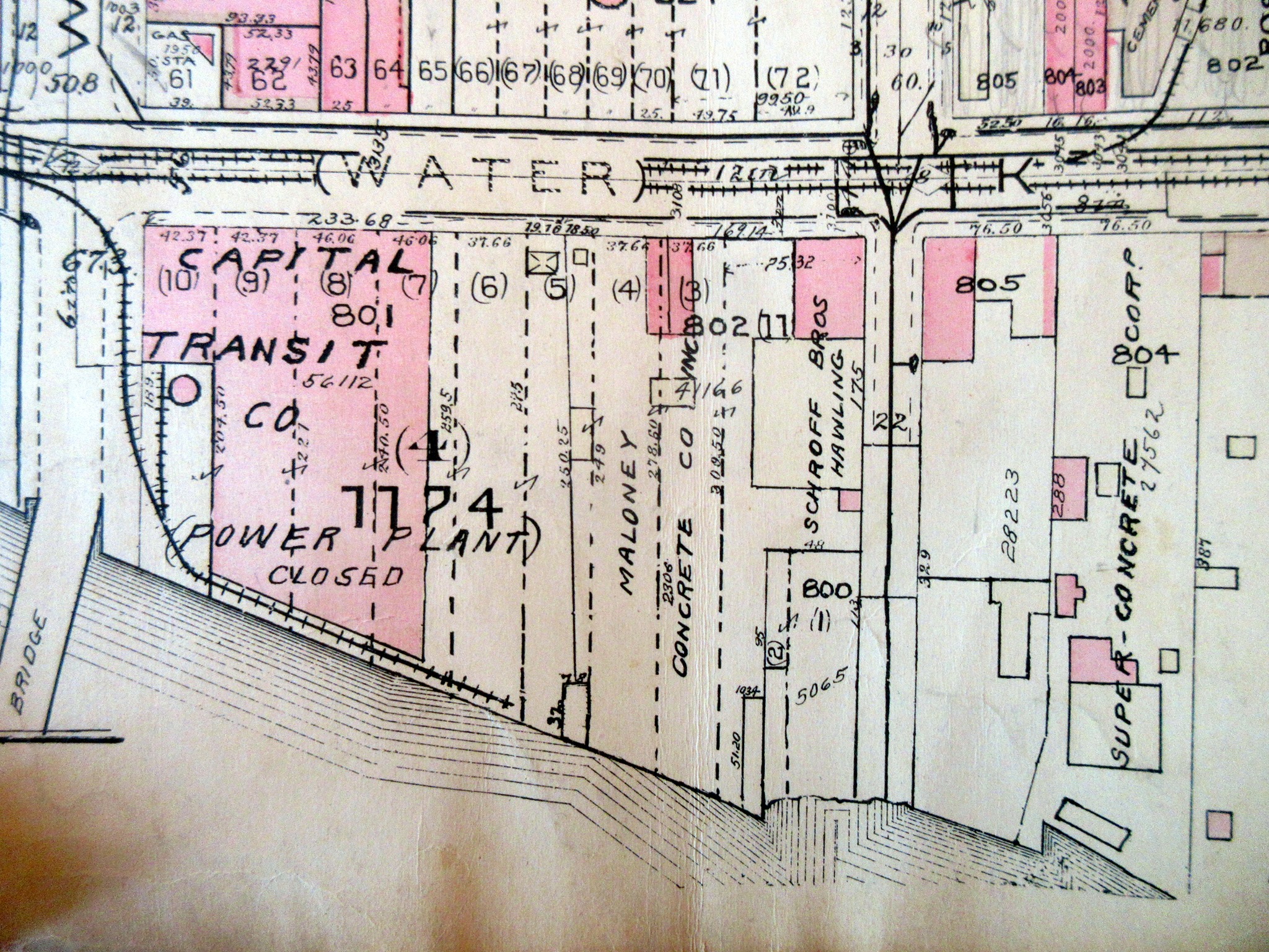
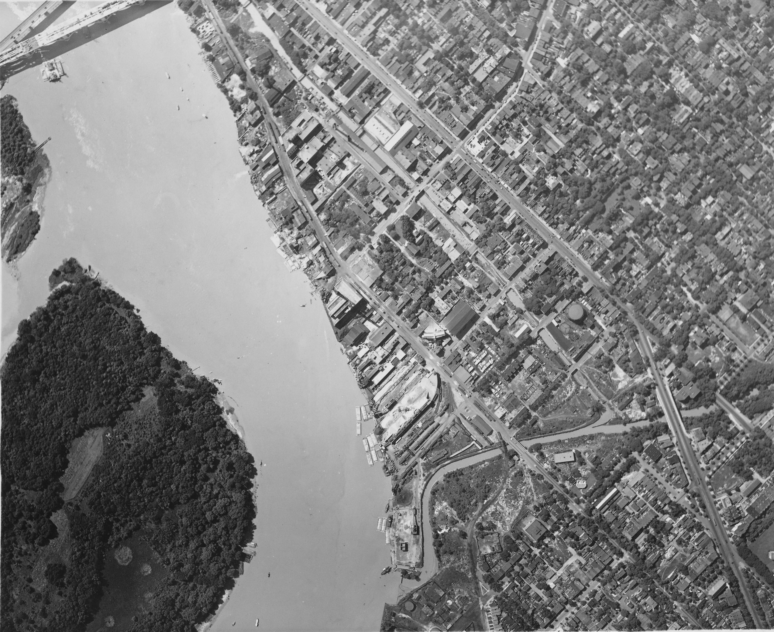
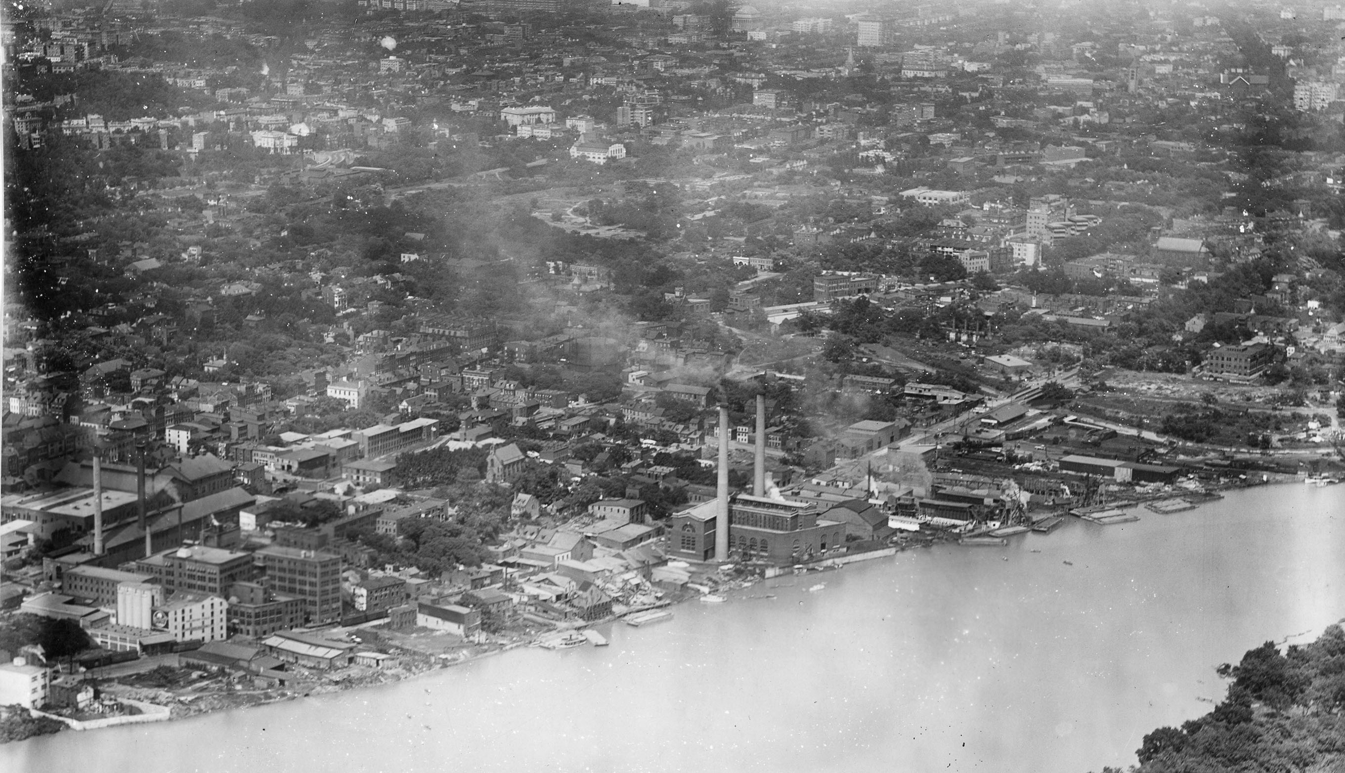
Another magnificent find from the National Archives. This one is a straight-down view of the heart of Georgetown. There are SO many things to take in here. Let’s have a look:
Hope you enjoyed this one. It’s a real rabbit hole! I have many more to share and will over the coming months. Would love to hear what you think of this awesome image!
I was tipped off by good friend and Archivist Nick F. to the large collection of aerial photos at the National Archives shot during the early-mid 1900s. The most challenging part of my research has always been this period. The line was finished in 1910 and at that point and up into the late 1940s personal cameras were not really a thing. Folks weren’t out there snapping photos of common things unless they had a reason. Photos were more intentional and administrative or commercial in purpose. The B&O had a collection of valuation maps and photos shot around WWI. Over time, when a project was enacted, they would take additional photos. Of course there were roster shots and things of that nature, and it was very much documentation. So, when I saw these images, which largely span from the 19-teens up to the 1940s, I was floored. They are a window into a world that I have yearned to see. It will take me a good amount of time to get through all of the images but I plan on sharing them here when I can. Enjoy!
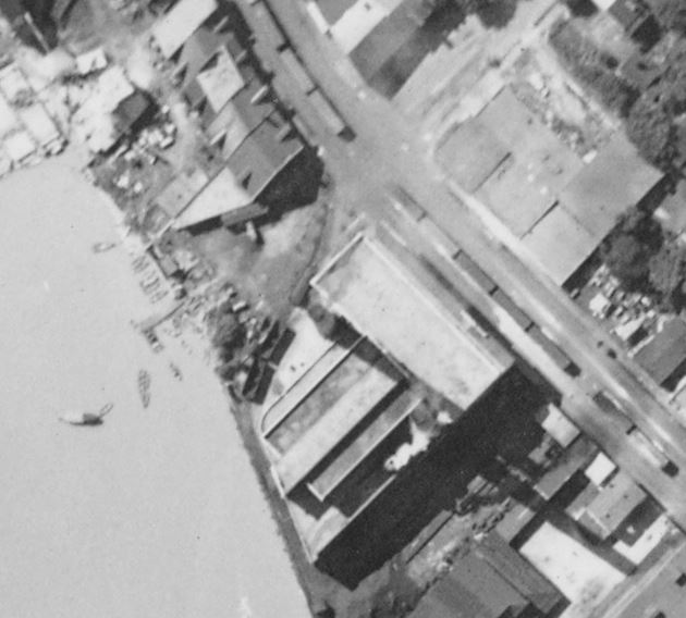
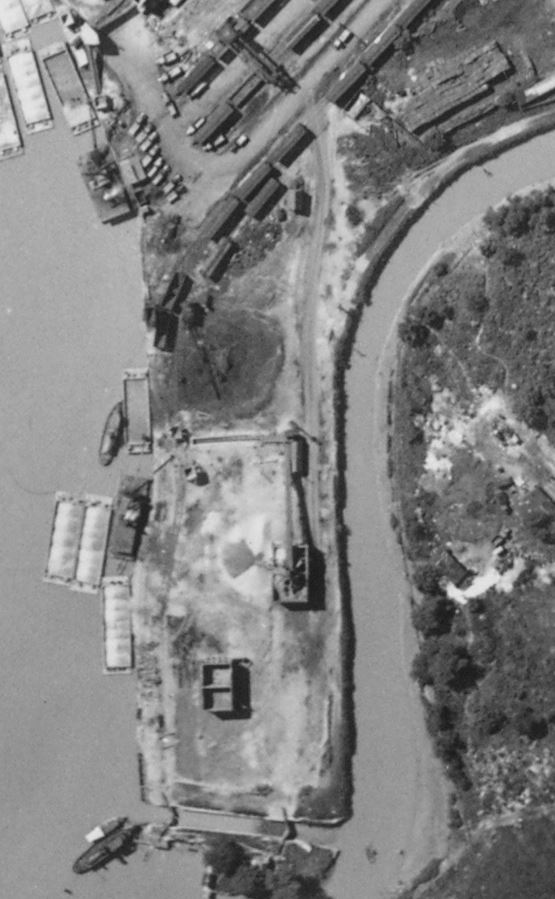
This first image is particularly interesting for a few very special reasons. Let’s start with one that I have been waiting for some time to see with clarity: the extension of the Branch that crossed Rock Creek and skirted along the Potomac to the construction site for the Lincoln Memorial. This siding made an appearance on the B&O Form 6 which listed all sidings along the line, but photos have been elusive. You can also clearly see the peculiar curved loading dock on the right side of the old B&O freight house located at the end of the line.
I also noticed that the Wilkins-Rogers Milling building looks very different and that is because this is the “old” mill that stood on the site until it burned down in a fire on July 4, 1922; a year or so after this photo was taken. There is a massive logo painted on the side of the mill which I believe is related to cotton production, which the mill apparently handled prior to being rebuilt.
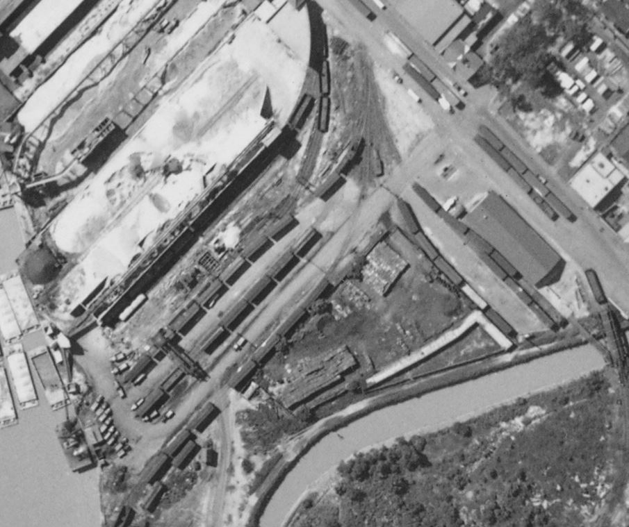
There are SO many other details to soak up like the track arrangements, the old Capital Traction power plant (perhaps loading coal from barges or undergoing some construction?), The “new yard” wouldn’t be built for another 20 years or so. This was a busy time in Georgetown.
In the prototype modeling world, I have heard many folks tell me that if I can’t find source data and photos of something, then I should go ahead and build a model of it, because you KNOW once I finish some brilliant photos and blueprints will surface. Anyone who chases ghosts of bygone eras in their research and modeling knows what I’m talking about. Thankfully, there are some wonderful folks out there like Brian R. who regularly volunteers at the B&ORRHS Archives and is also a friend who knows what my model RR project entails. He reached out to me last week with three absolutely incredible photos. (Apparently there are more! I really need to get myself back to the Archives for more digging.)
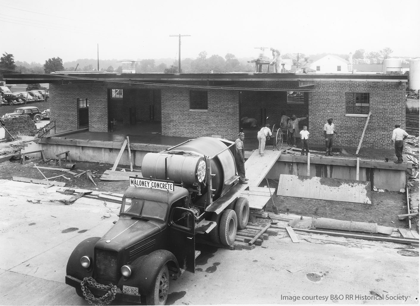
A bit of back story – Bethesda was really not much of anything when the RR came through town in 1910. Most folks in the rustic community saw it as a nuisance and impeding on their bucolic suburban hamlet. However, growth was inevitable and in the late 1930s with DC suburbs seeing lots of expansion, the B&O obviously realized that the crossroads in Bethesda were a great spot for a hub of fuel dealers, concrete plants and lumber yards and freight facilities to be located. A depot was needed. In the Spring of 1941 the railroad began construction on the depot, completing it a few months later in July. Oddly enough, they chose to build a freight house adjacent to the tracks with no provision for a connection to the railroad. Yep, take a good look at the Bethesda freight house and try to figure out why it was designed the way it was. No tracks lined up to it for trans-loading. It has a nice broad raised platform for vehicles to unload/load on, but no railroad connection. An oddity, for sure. What proceeded the brick depot is a mystery to me. Any info would be most welcome. Enjoy the following photos, courtesy B&ORRHS.
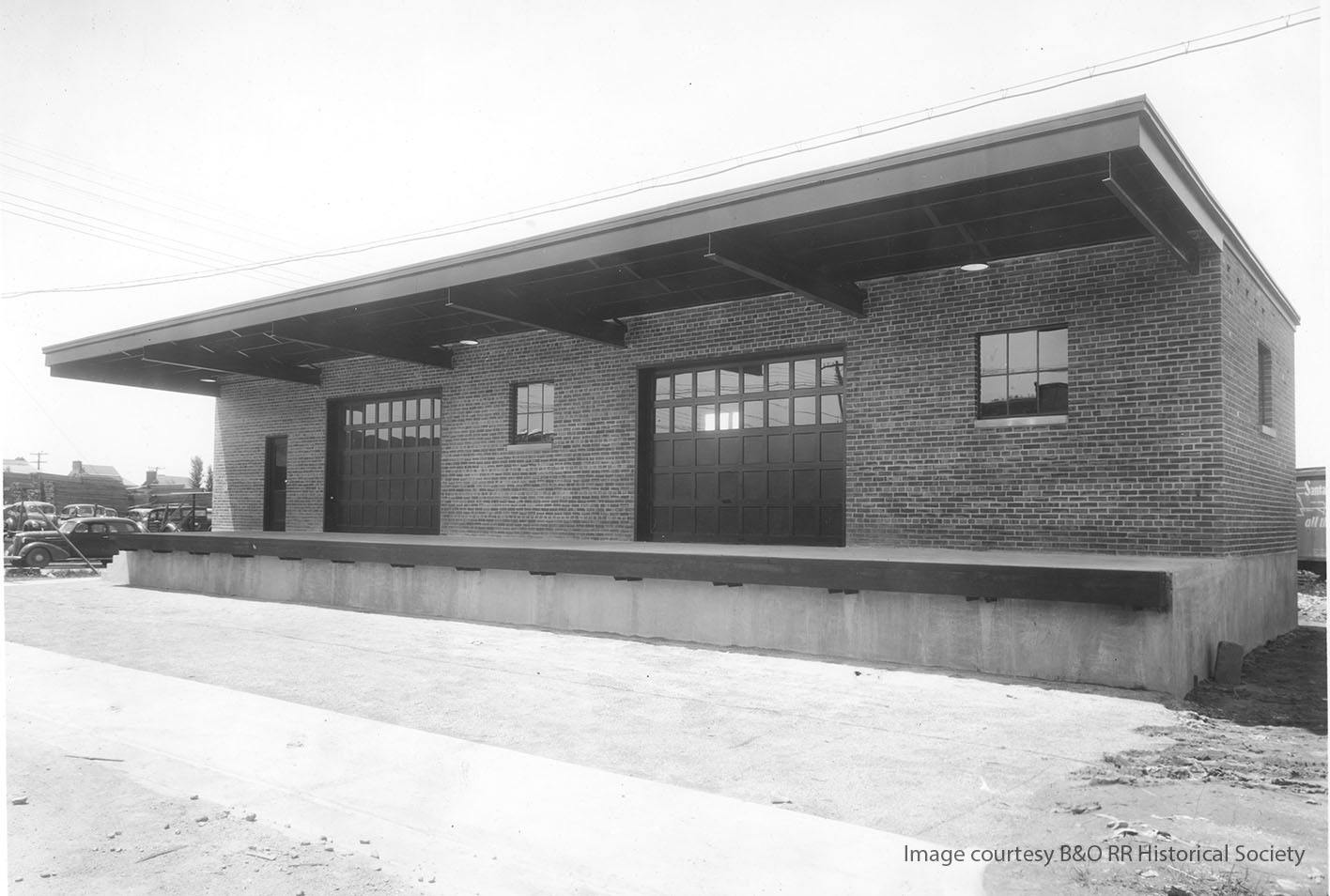

As a sidebar, some of the blueprints I used to make my own model and drawings were also from the B&ORRHS and I shared them here:
https://www.flickr.com/photos/cpl_clegg/albums/72157687317143670 These include blueprints for the railings, iron work, roll up doors, windows and concrete flooring/footings.
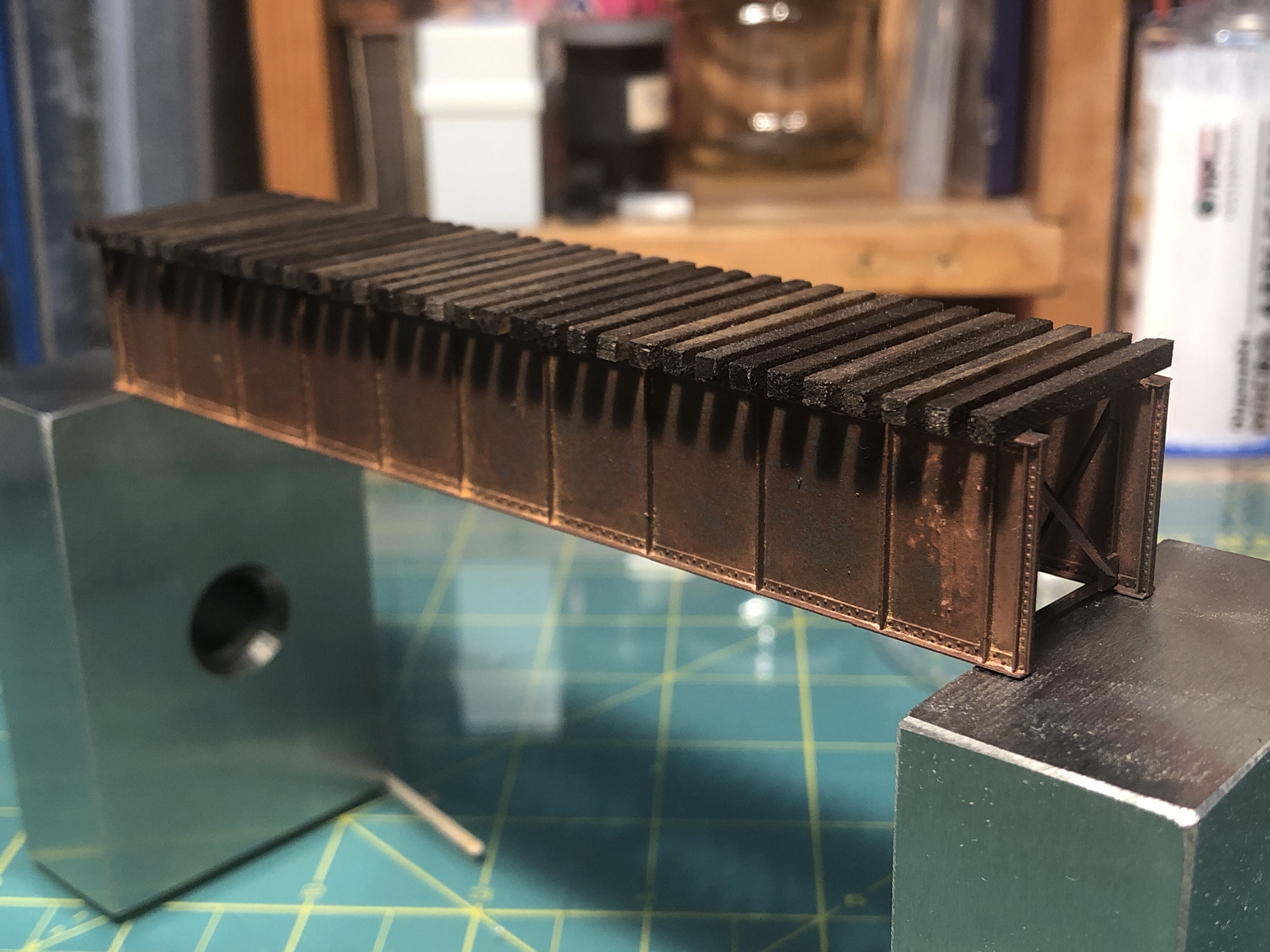
Making headway. Details on the build coming later. Here’s a teaser.
Some will recall that the Purple Line folks intended to preserve and display the old girder(s) from the Talbot Ave bridge. They have just posted an artists rendering of what the old girders will look like at the Lyttonsville Station. Pretty neat. I’m just glad they were preserved!
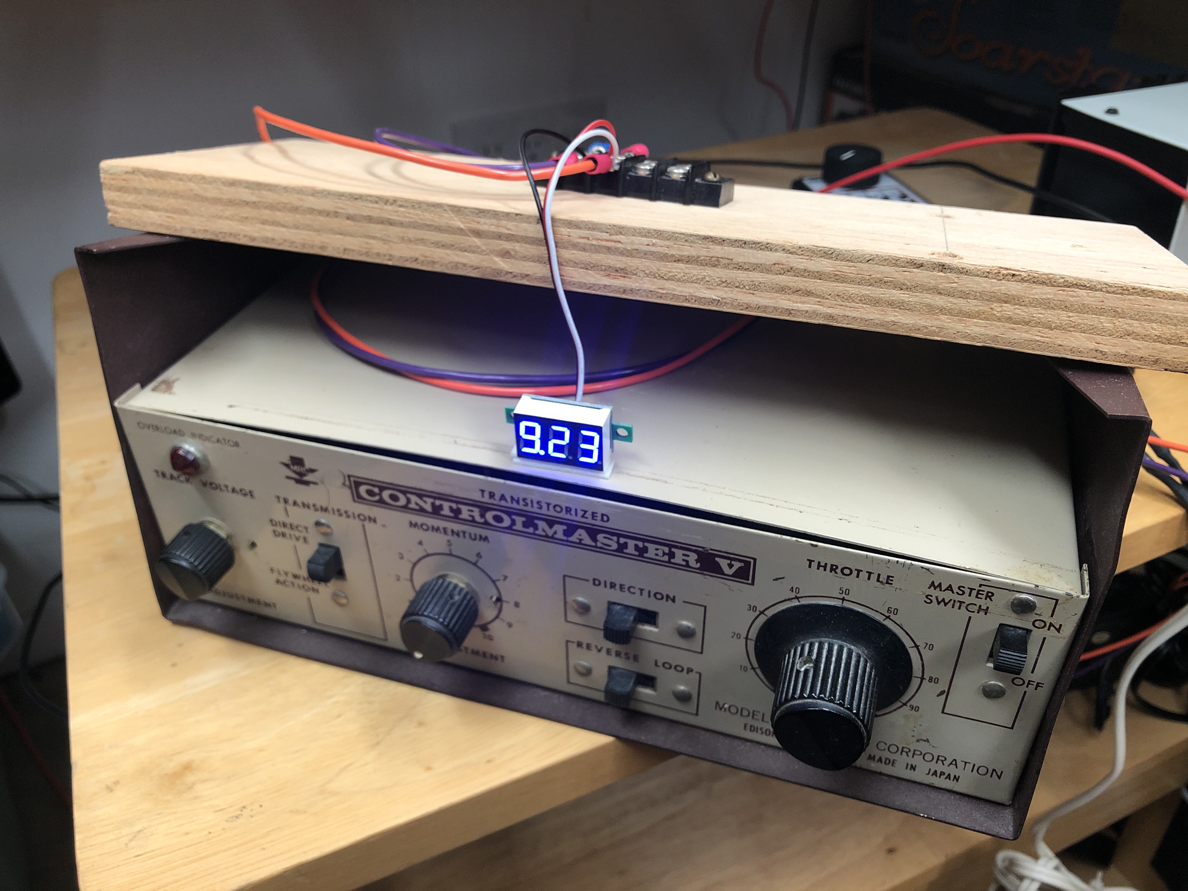
Picked up a five pack of these tiny DC voltmeters to track voltage on my accessory bus running switch machines and lights. It’s a nice blue color and is working well so far.
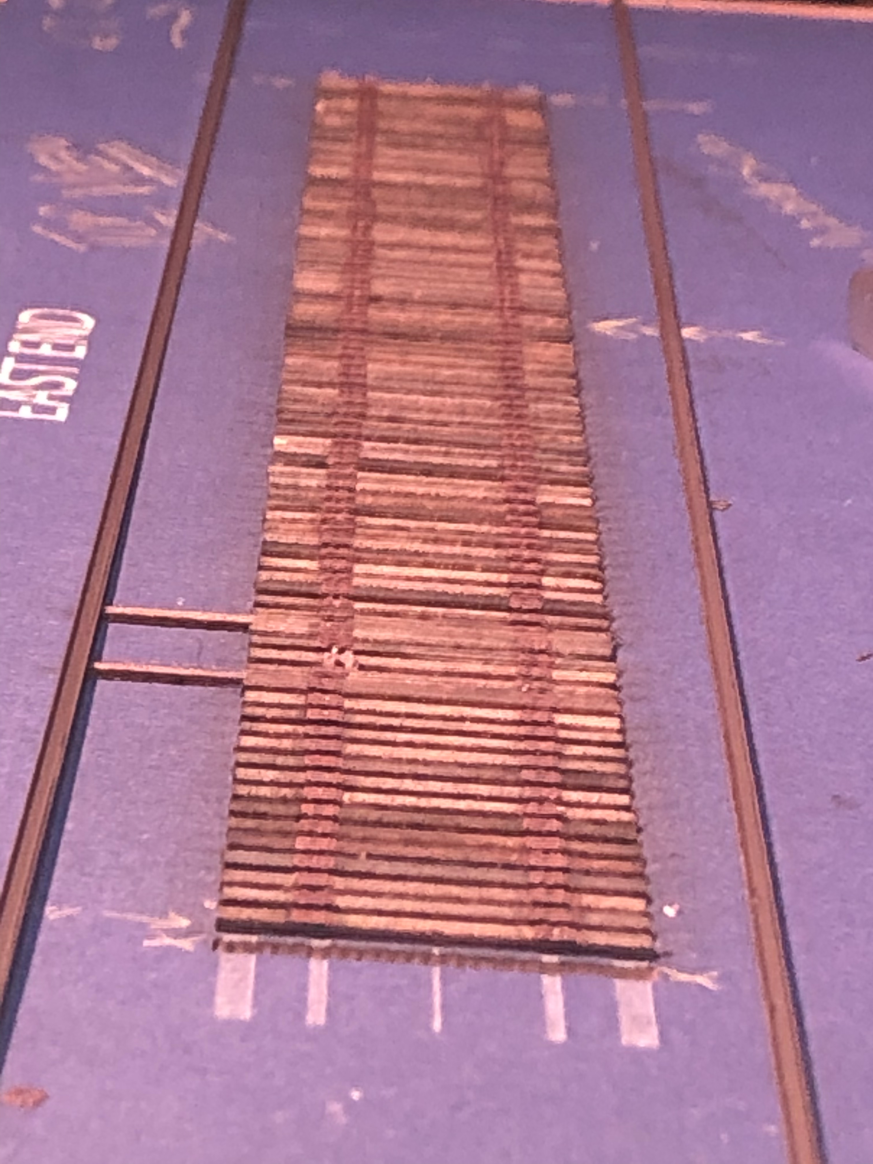
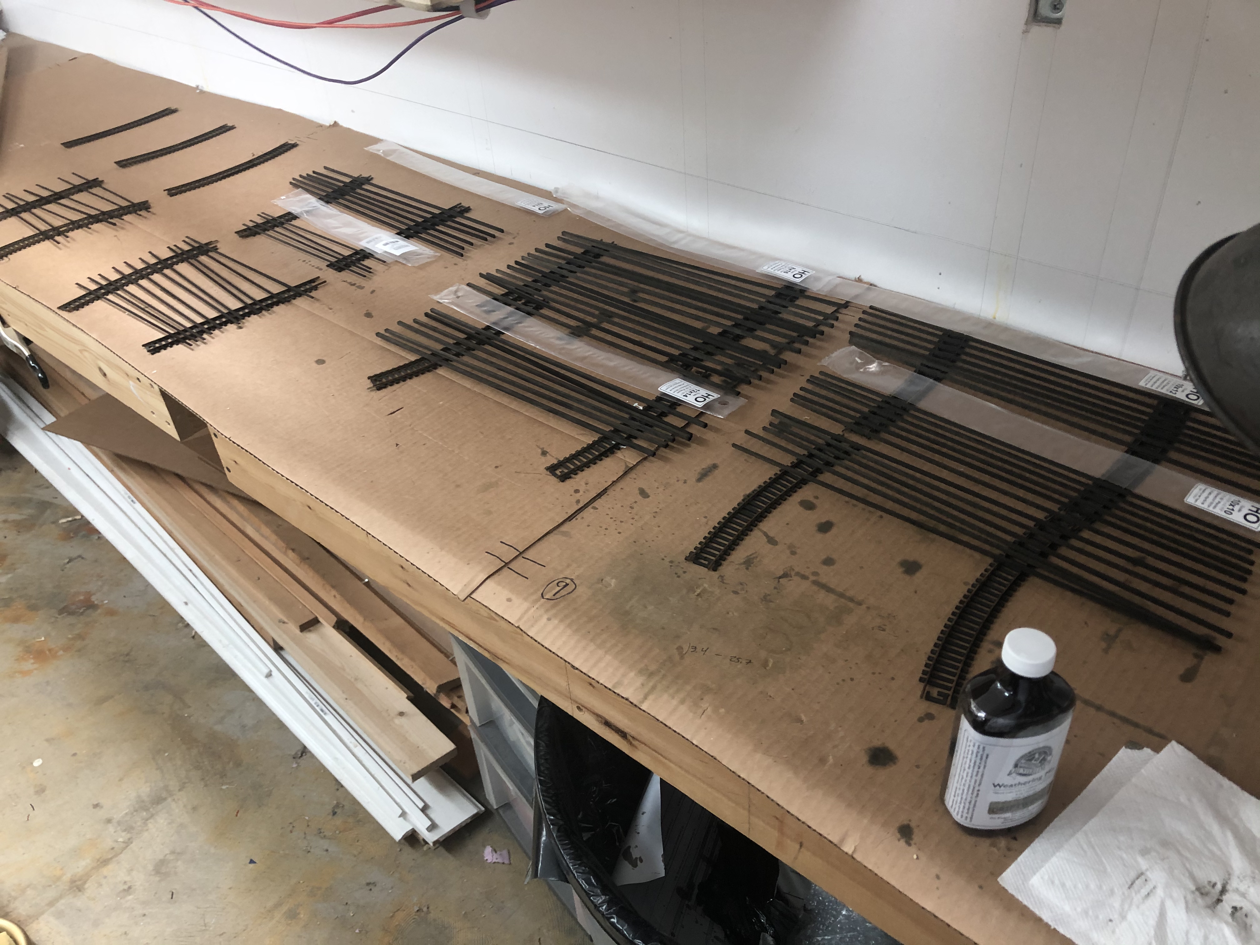
I have spent a good amount of time over the last week working on some new and some old projects. I made another revision to the Rock Creek Trestle plans after discovering a new photo showing how the top of the bents appeared. I adjusted one of the beams and shortened the ties, as I realized I used the wrong length in my plans. That is all corrected. I also stained all of the new wood I received a few days ago and have that drying.
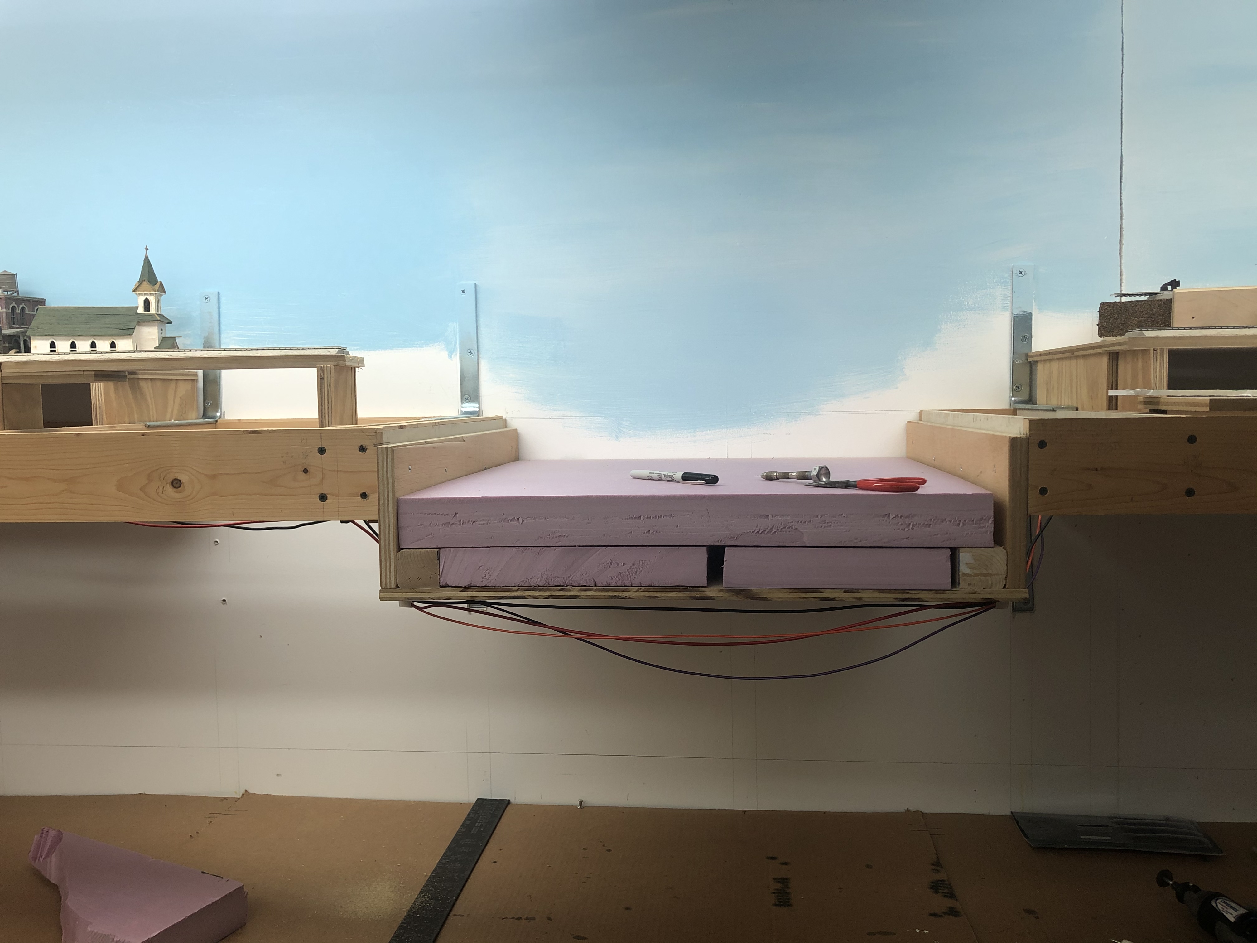
The biggest change to the layout is the removal of the temporary bridge across Rock Creek in preparation for scenery construction as I begin building the trestle. I also installed two plywood panels below what will be T.W. Perry (on the left) and some scenery support on the right.
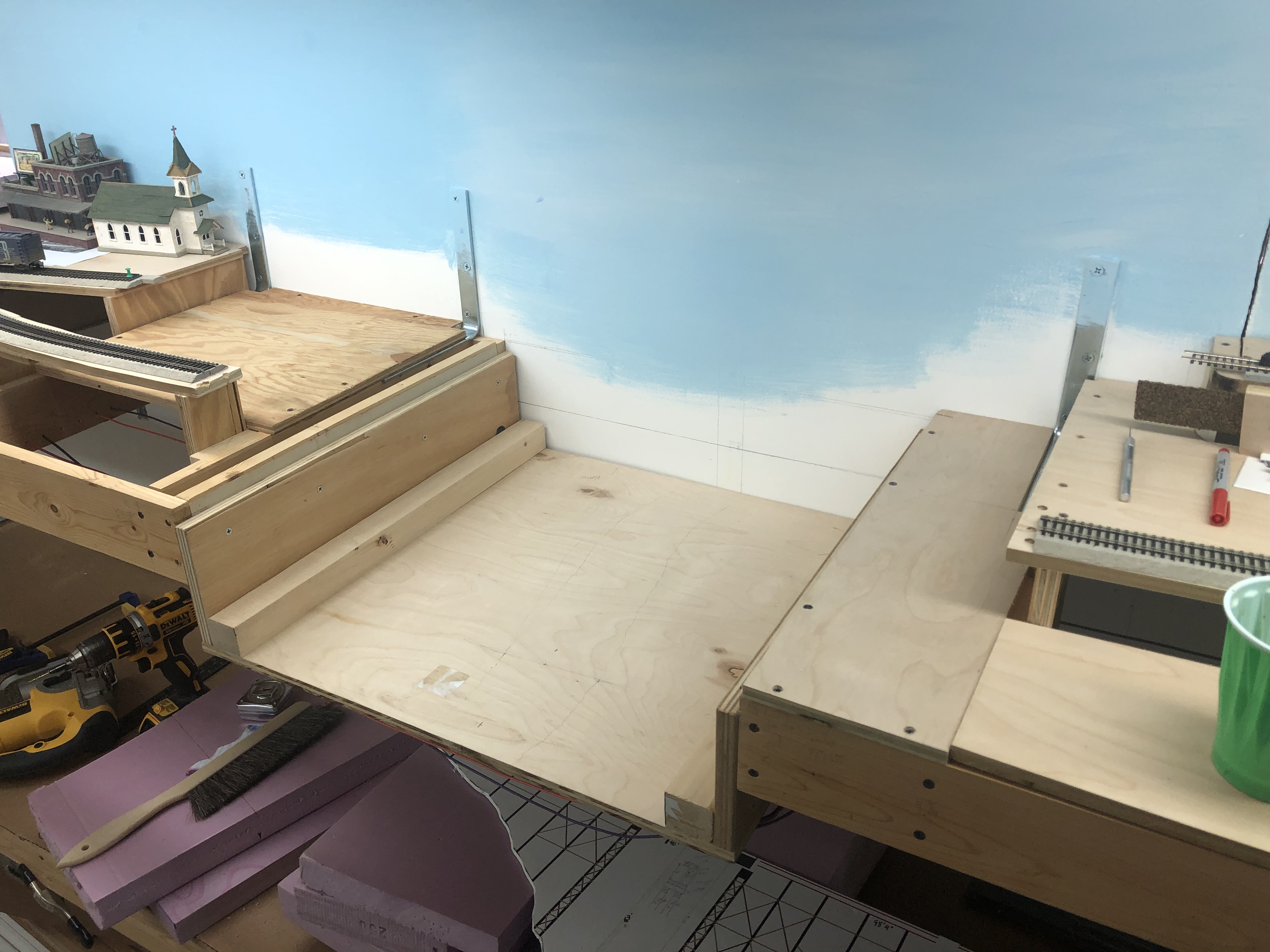
Installation of the trestle has been a real conundrum for me. If it was a frame structure, or made of iron, it would be a lot easier. I could build the scenery, carve away some plaster, install some “concrete” bases for the bents of the trestle and let it sit in place. Adjusting the height of the footers would be pretty straightforward. But this is a pile trestle, meaning that the round piles were driven into the ground. There is no “base.” The base is dirt. How do I install the trestle into the ground with the hope that some day I could remove it from the layout and preserve it? I have settled on building “steps” made of high density expanded foam board cut to specific thicknesses for the trestle bents to rest on. This will all be glued together and will be about as wide as the trestle and will span the gap of the layout. Once I build this base, I can carefully build up the scenery around it. I will use Howard Zane’s method of rosin paper and white glue with cardboard strip supports and then Sculptamold and plaster on top. If I need to remove the trestle, I can trim the hard shell and extract it. I experimented with foam for the base, but decided against it as I don’t have a good way to cut it and maintain a strict landscape profile that I want.

Remember those MRServo units I mentioned in the last update? Well I kinda went down the rabbit hole on those, too. I purchased eight of the now-discontinued MRServo-1 units. I believe they started using the board from the MR-Servo-2 and -3 units for the -1 toward the end, because that’s what I have. In reading documentation for these units, I learned that all they are missing are a couple of relays and terminals to convert them to MRServo-3 units. So after quite a bit of hunting and comparing specs and photos, I dug up the correct relays and terminals and ordered a handful from eBay. Will attempt to convert them later this Spring when the parts come in. The conversion will add power routing for turnouts and power routing for accessories.
I spent some time talking to Greg C. about structures in Bethesda. I want to model a few key structures and Greg is an expert in structure building. He has been helping me push through the mind block that is planning what to model and how to do it. Right now, I am studying photos and mocking things up to start to get proportions and ideas.
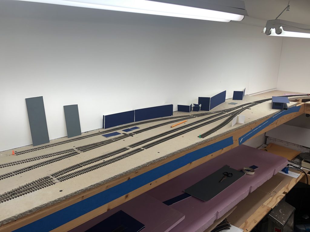
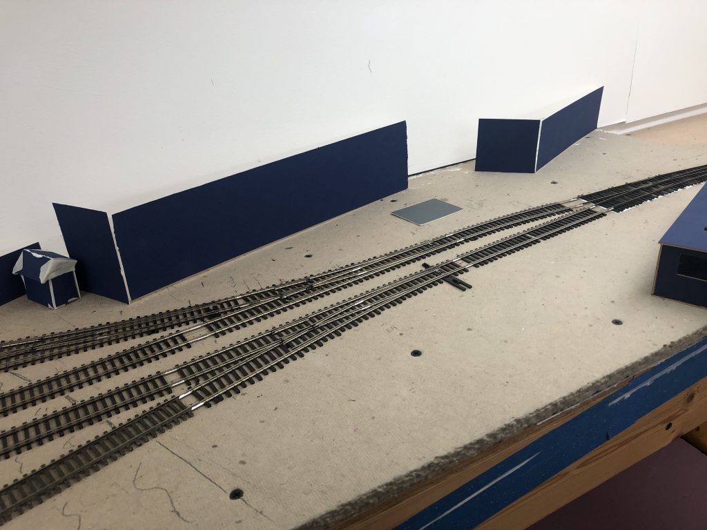
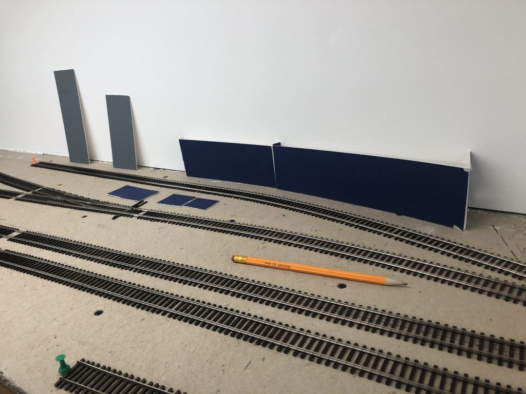
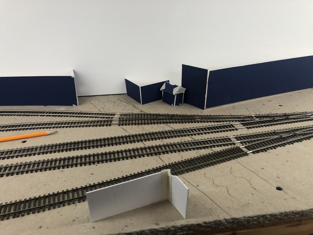
These are meant to be super rough ideas. I just cut apart some mat board scraps I had laying around and taped them up. It’s to get the brain going on where I will eventually place things. Also gives me an idea for any drawings I can start working on for structure walls. Some of them will likely be custom jobs. That’s all for now!