Over on Lance Mindheim’s wonderful blog, he developed a track plan design for the Georgetown Waterfront that fits on a small L-shaped shelf. I really like this plan and think it captures the essence of the waterfront in a very small space. For me, the most fascinating thing about the waterfront in its heyday was the multitude of industries and how the B&O served them.
The track plan covers a lot of the industries and yards represented in Georgetown and would make for engaging and interesting operations. I could see the Georgetown Turn has left its string of cars on the long siding (staging) and the switcher is tasked to pull the cars onto K St. and begin classifying them. Meanwhile the empties are being rounded up and built into a train for the Turn to bring back to Eckington. These cars would be spotted on the staging track. The switcher then goes back to focusing on spotting all the loads that just came in. If another track could be added to the staging yard, a second “Georgetown Turn” train could be spotted there for the switcher to pull into town and work on, as the cycle would start again. Hours of work here to do. I dig it!
I know I haven’t posted in a while but as the Spring approaches, things are getting busy around here. Work has been nuts. HPDE season is upon us and I’ve got my first event at Summit Point with the Audi Club this coming weekend. Track prep time! Here’s the update:
Layout progress has been focused on cleaning up, organizing and working on the Rock Creek trestle, as well as devoting a large amount of time to working out the operations scheme in JMRI Operations Pro, with lots of help from Kelly R. The cleaning and organization tasks were accelerated by a visit from Ken & Bill from Spring Mills Depot. Ken and I chatted at the Springfield show and decided to get together to see each others’ layouts and share progress and lessons learned. It’s been very motivational seeing what Ken is doing and having them visit my layout to talk about my own process and future goals. I’ve got lots of good energy to move forward with.
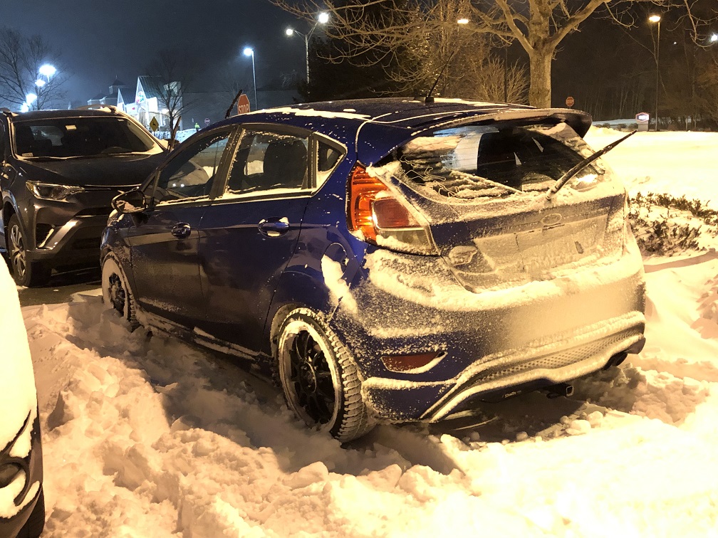
I drove up from MD to Springfield to attend the big show with my cousin Eric. Here’s the status on the evening of the first day. It wasn’t too bad in Springfield compared to eastern MA, but it was still an adventure!
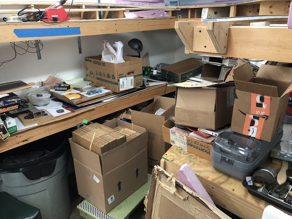
Coupled with the layout visitors, I have also been selling a lot of extra stuff on eBay. Over the last year or so I’ve really culled a lot of rolling stock and material from my collection. Much of it was sold at the GSMTS Timonium show, but much of it has been sold via eBay. As I clean and dig through my things, I find more and more to list for sale which really helps motivate me to continue to refine my focus and standards for the layout. Also, the sales help pay for the layout materials and new freight cars that I come across. Here’s a photo of the layout from a month or so ago:
The layout became staging for eBay sales for a few weeks.
JMRI progress has been a real roller coaster. Yesterday morning, in a fit of frustration, I was ready to swear off the program (both literally and figuratively) after running up against a string of constant, baffling errors. Kelly talked me off the ledge and offered to help rebuild and refine my layout concept in the software. I’ve realized that JMRI is going to be the best solution for what I want to do with the operations scheme on my layout; it offers pretty much all that I want, even though I have a long way to go before I get to my goal. I do have a document which outlines all of my “givens & druthers” as well as rules, specs and other details about my scheme. This will be published later for anyone who’s interested. Also, if anyone wants to talk Operations or JMRI, please reach out! I’m neck-deep.
A byproduct of the layout visitors and the JMRI work I’ve been doing was that I put together manifests for four trains that I refer to as the “Bethesda Turn”, since Bethesda is as far as the track currently goes on my layout. After the visit, I ran these four trains as I intend to run most of my trains, and it was fantastic. Yeah, not all the switch machines are in place, and some of the frogs aren’t wired, but the overall feeling of what it will be like to operate the layout was there, and it was really cool. A taste of things to come.
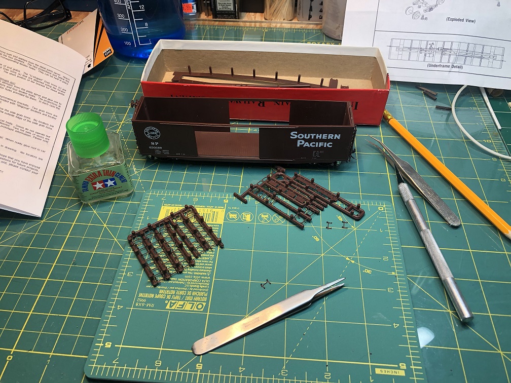
I find that in this hobby it’s important to have active projects in different areas of the hobby to keep things interesting. Last month when I got tired of installing DCC decoders and building trestle bents I switched over to building a freight car kit. The one I chose from my shelf-o-unbuilt-kits was an old Intermountain PS-1 50′ Double Door Box Car lettered for Southern Pacific #650159, kit #40607-10, with a 1955 build date; just inside my era. I found this kit on the shelf at the Annapolis area LHS, Star Hobby, for a had-to-have-it price of $10. Side note: I-M seems to be taking reservations for a re-release of this kit right now!
Trimming the grab irons from the sprue. A fresh blade was a necessity here.
I hadn’t put together a challenging kit like this in many years and I had a blast. I upgraded it with a Kadee Apex running board, some Tichy end grabs and Tangent ASF A-3 wheel sets. (The prototype apparently had Symington-Gould A-3 trucks, but I haven’t found a manufacturer for those in HO.) The kit didn’t come with instructions, but thankfully I found some on the I-M website. It’s really nice they put the instruction manuals up on their site!
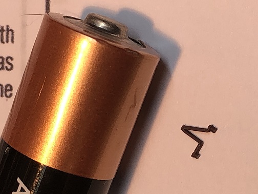
This particular bracket decided to liberate itself into thin air as I was attempting to install it. I searched and searched and eventually gave up. The next day, I found it nearly straight away below my workbench. Huzzah!
Car weights came in the form of wheel weights I collect off the ground at track day events, which I glued to the interior floor with Liquid Nails. The body was badly warped at the top and required careful attention to straighten when gluing to the roof. The doors were also ever-so-slightly warped but once in place looked fine. All in all, a neat car. I don’t have many 50′ cars so this one will look nice delivering lumber to Galliher Lumber in Georgetown.
Lastly, a word about the NMRA Achievement Program (AP). Over the winter I was inspired to begin participation in the various AP areas. A few of the folks in my club are diving in and working toward their MMR so I figured I’d join the journey. So far, not a whole lot of movement on my end. I’ve started organizing and reading through the materials but that’s about it for now. I just haven’t been making this a priority, as I’ve had other things going on requiring attention. However, I have been taking photos of some of my projects in preparation for writing up articles. I will definitely post links here once that materializes. For now, I’ll keep planning and aligning my modeling efforts with the various AP certification qualifications. I think of it like merit badges for adult model railroaders. I’m enjoying the challenge!
Like I said, this is just a quick, off the top of my head update. I am hoping to be able to post more, but with work being so busy and other things vying for my time, I do what I can when I can. Be well and keep in touch!
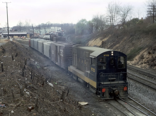
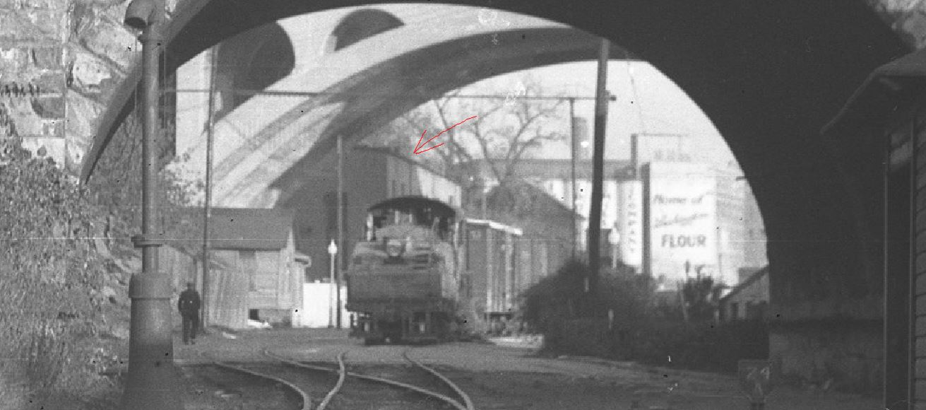
B&O 9725-1 Silver Springs [sic] MD 04-05-66, By RNS
This wonderful photo by Russ Strodtz on Flickr came via Jeffrey Sessa over on the Maryland Division Railfans FB group. My money is on the train likely being a load of empties coming off the branch, perhaps from Maloney in Georgetown or Bethesda. Curious if they’ll pick up some cars from the Junction and head East or pick up loads and head back to Georgetown. REALLY neat view of the E.C. Keys lumber shed in the background. Gives me some great info for when I build that model! Thanks, Jeffrey!
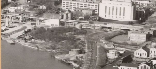
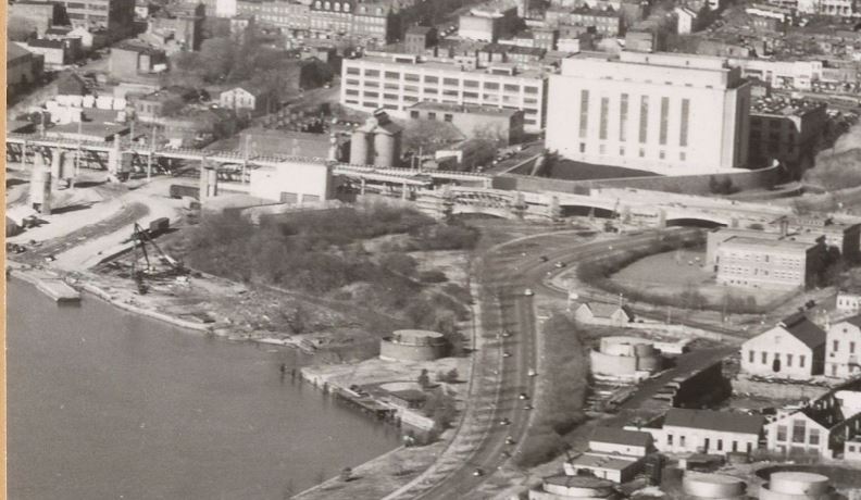
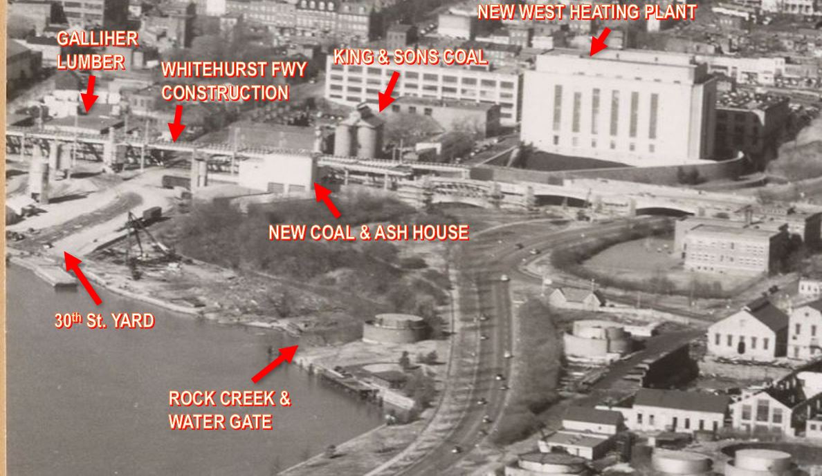
Selection from image: National Archives Identifier: 68153293 Series: “Airscapes” of American and Foreign Areas, 1917 – 1964, https://catalog.archives.gov/id/68153293
While perusing the wonderful Airscapes of American and Foreign Areas collection on the National Archives site, I came across this image of the Lincoln Memorial and vicinity. In the back corner, we get a nice view of some new buildings at the East end of the Branch as well as seeing construction on the Whitehurst Freeway well underway. In this image from January, 1949 we see the new West Heating Steam Plant and associated Coal & Ash House, which was turned out to be the last customer on the Branch until the last train in 1985. We see that the spit of land at the tail end of the yard, known as “The Mole,” has been nearly fully vacated save for a stiff-leg derrick crane.
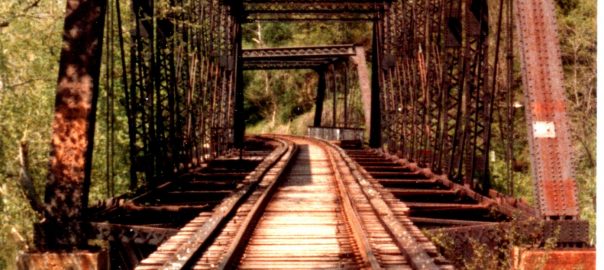
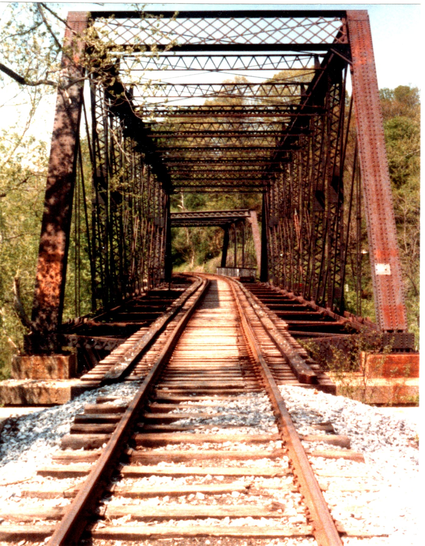
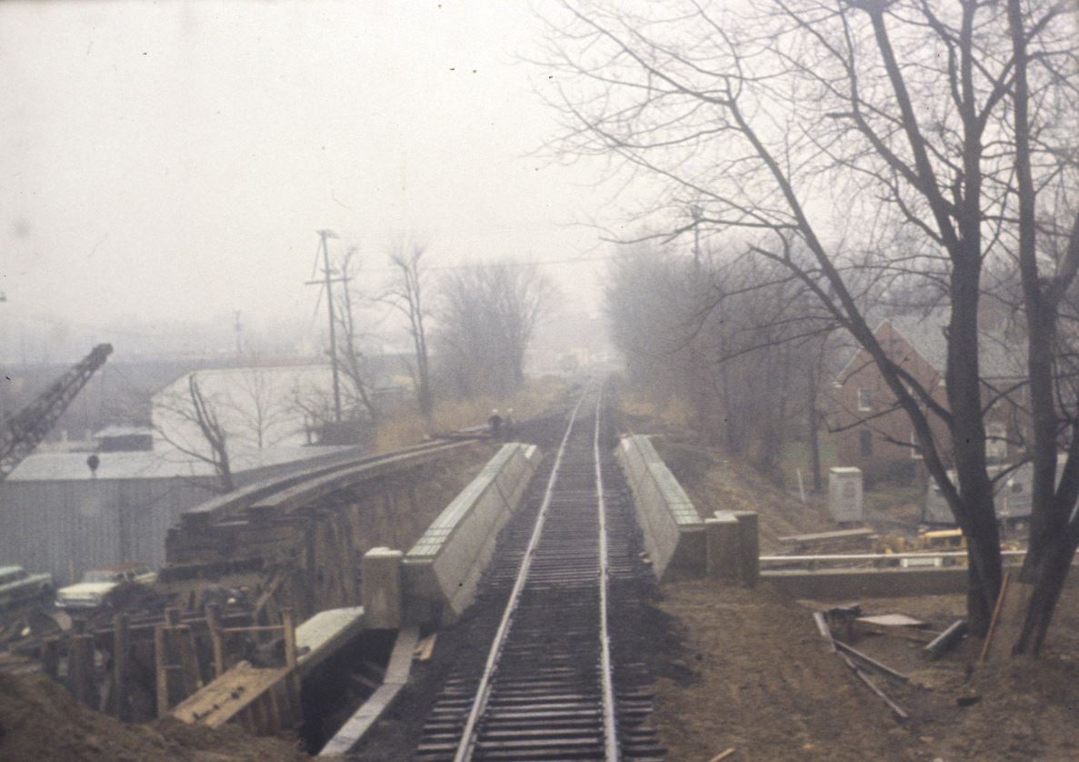
Christopher Russell sent me this neat photo of the C&O Canal trestles shot in the summer of 1986. Of particular interest is the fresh ballast and what appears to be girderwelded rail. As far as I know, the last train down the Branch happened in the summer of 1985. I had also heard rumor that Chessie/B&O decided to lay girder rail just before the abandonment took place. Maybe a case of the left hand not knowing what the right hand is doing? I know the Tom ThumbJohn Bull operated on this stretch in 1981 and thought maybe it was something similar. Anyone have any ideas? Was there a film or TV show shot on this stretch? The track would have been serviceable through the late 1980s so it could have been anything. Would love to hear your thoughts!
NOTE: Thanks Christopher for the corrections. I think I wrote this in a hurry and neglected to proofread it. Mea culpa!
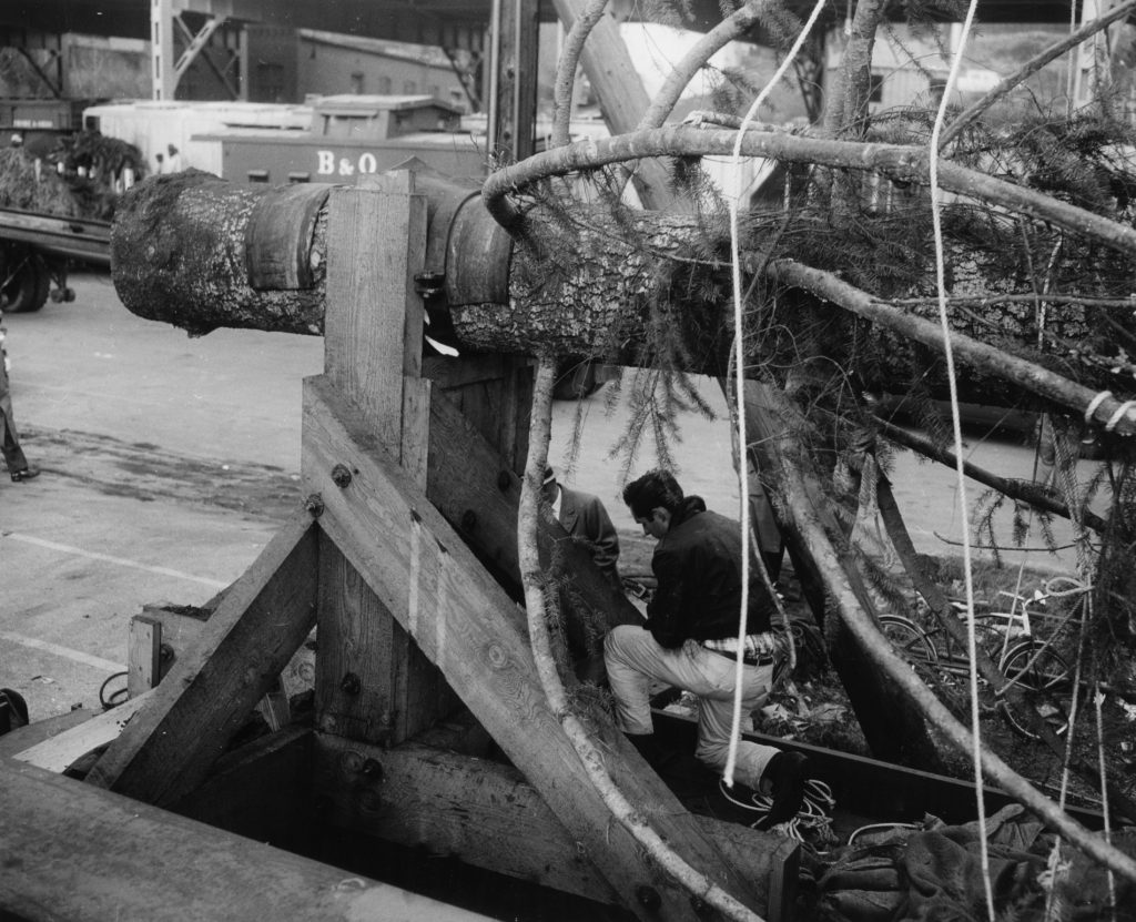
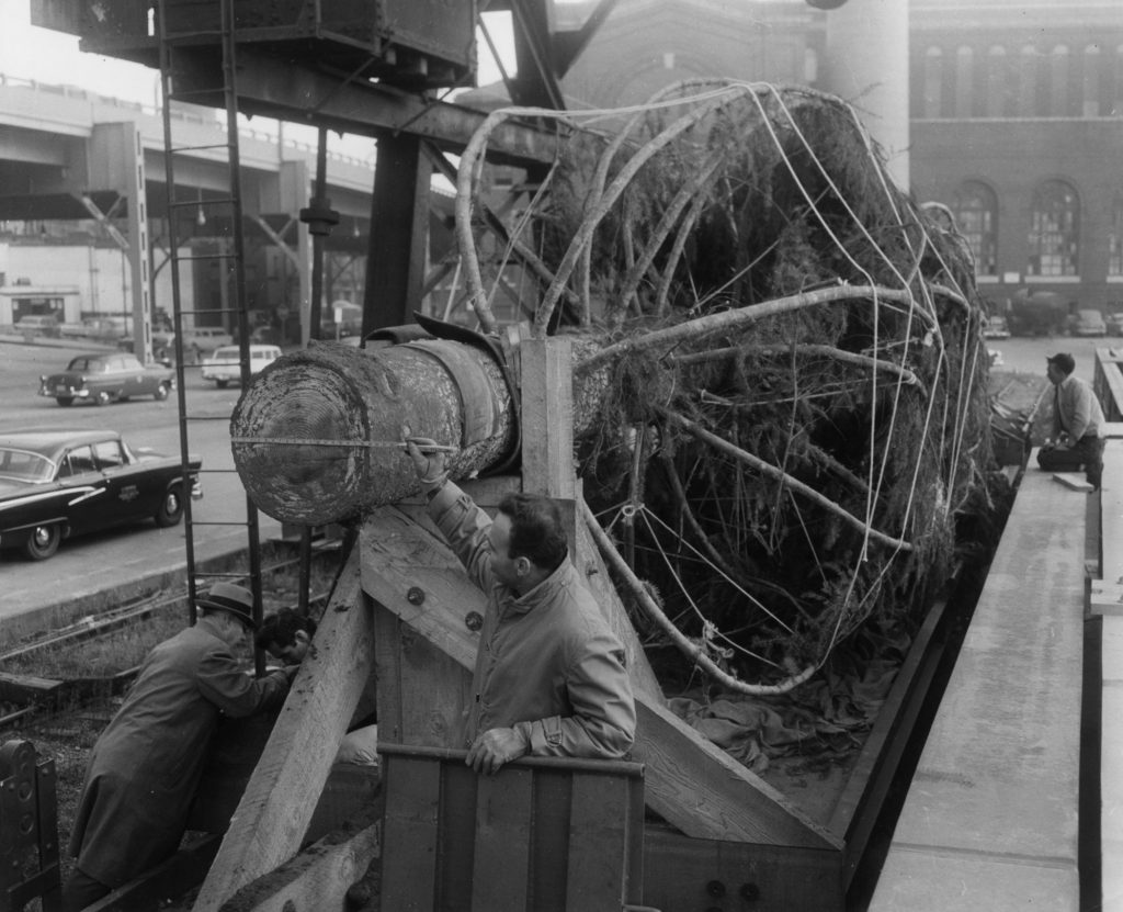
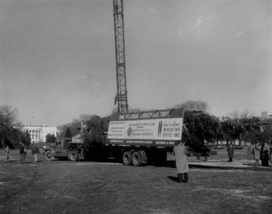
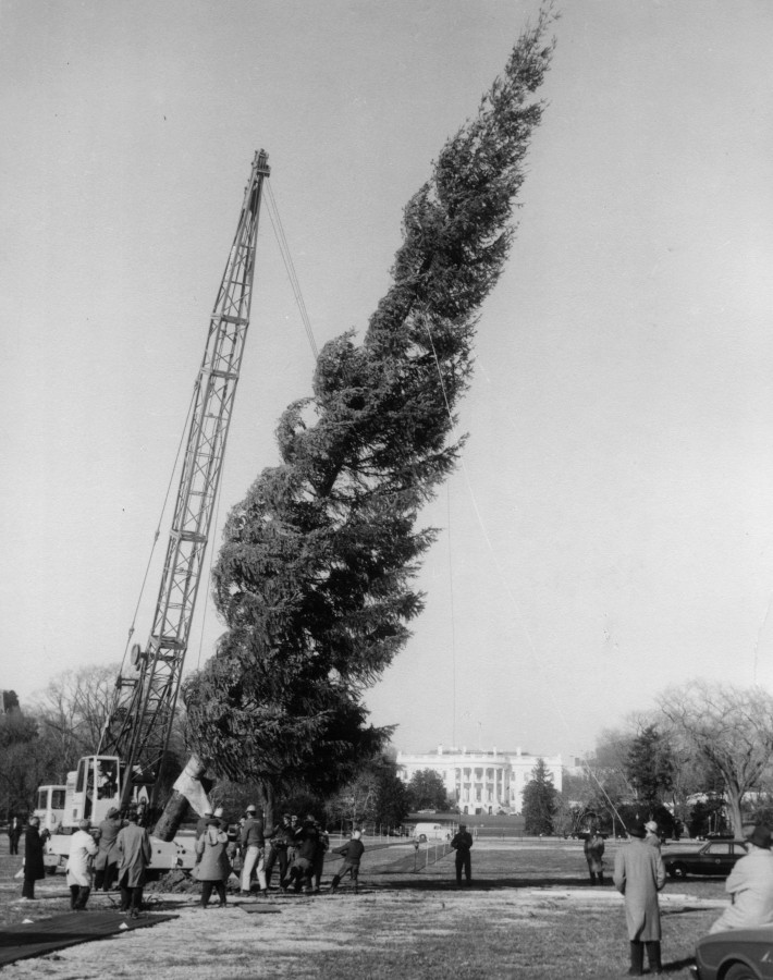
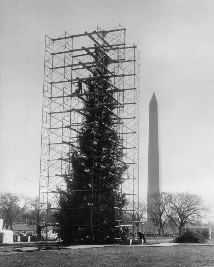
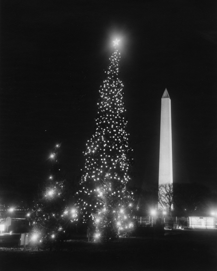
Over the years, I’ve shared a few photos I’ve come across depicting the National Christmas Tree resting in the B&O yard in Georgetown. (one, two, three) Beginning in 1954, the “Community Tree” would make its trek cross-country on a flat car or gondola; blocked, braced, packed and tied-up like a Christmas ham, the tree would arrive in DC to be transloaded onto a flatbed trailer and trucked through Washington to the National Mall where it would be craned into place, decorated and illuminated as the star attraction in the Pageant of Peace.
I was recently contacted via email by a member of the Forest History Society who so generously shared some photos (and a video!) related to Christmas trees in Georgetown. These images are REALLY cool and show some views that I’d never seen before. I am always really excited whenever I get to see new things related to the Branch! You can see all of their National Christmas Tree related images in their archives, here. They recently published a wonderful article on the journey the 1961 National Christmas Tree made from forest to the National Mall.
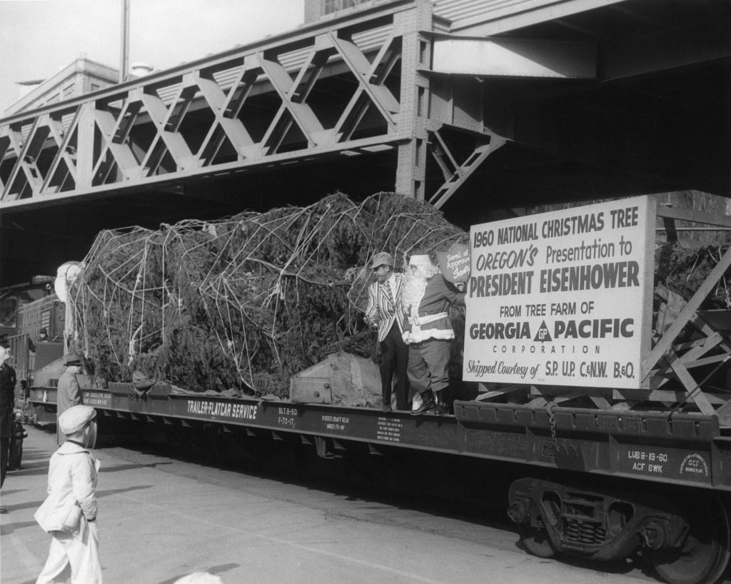
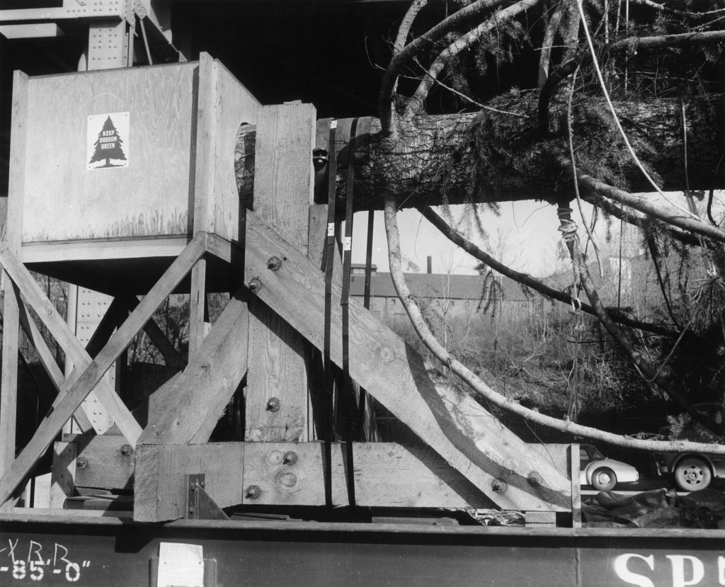
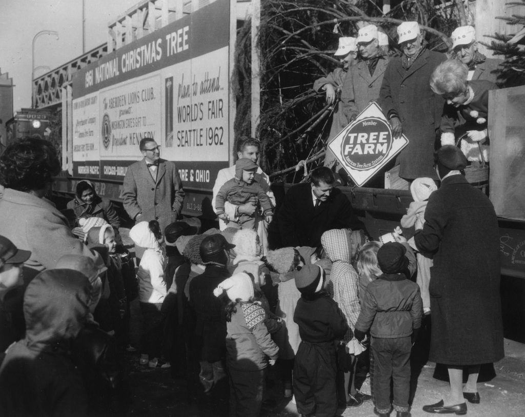
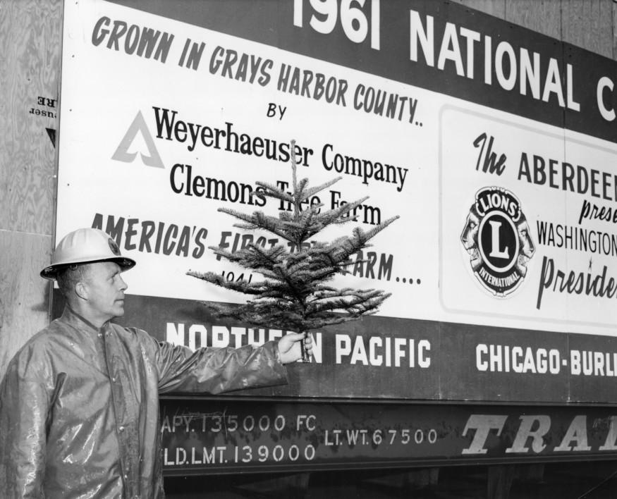
In these photos from FHS we see the 1960 tree having arrived in Georgetown being tended to by some staff members. This tree was cut in Oregon and traveled via SP/UP/CNW/B&O on an SP F-70-17 85′ flat car. In the first photo we see what must have been an arrival ceremony and even Santa has climbed on board and is wielding a “Seal of Approval” sign. In the next images we can see a large box surrounding the end of the tree, no doubt to protect it and keep it wet. We then see the tree being prepared for transloading to the adjacent flatbed trailer. Bonus video footage of the tree being prepared in Oregon for its voyage across the Country. The final images are the 1961 tree which came from Grays Harbor County, WA via NP/CB&Q/B&O on a TTX flatcar. All photos are courtesy of the Forest History Society, Durham, N.C.
Christmastree arrival from Oregon
G-P 1960 NationalChristmasTree
G-P 1960 NationalChristmasTree
G-P 1960 NationalChristmasTree
Arrival of 1961 National Xmas Tree
1961 National Xmas Tree shipment
Film footage of cutting of 1961 National Christmas Tree (film has no sound). The 1961 National Christmas Tree was a 75 foot Douglas fir grown on Weyerhaeuser Company’s Clemons Tree Farm in Washington State. The tree was shipped by rail to Washington, DC, where it was erected and displayed on the Ellipse. This film footage shows cutting of the tree in November 1961, and the ceremony at rail yard prior to shipment. Film is from the Weyerhaeuser Company Records held at the Forest History Society: https://foresthistory.org/research-ex…
The National Christmas Tree tradition stretches back to 1923 but in 1954 the decision was made to do something more extravagant and impactful to woo more tourists to the area and do something really special. The Pageant of Peace was born, a celebration of the holiday season that included music, art, and lights, with the centerpiece being what was being called “the National Community Christmas Tree”, culled from the great forests of America and erected on the National Mall where the Pageant and “Pathway of Peace” display would be located. There were national displays, international exhibits, participation from civic and religious organizations and all sorts of activities for children and adults alike. Over the years, the Pageant transformed and changed with the times. Some years it reflected a more somber national situation; in 1963, after the assignation of Pres. Kennedy, the lighting of the tree was delayed for several days to allow for a period of mourning and a more somber ceremony followed. Some years it was befallen by delays and problems. In 1970, the tree came from Nemo, South Dakota and along the way it derailed twice; once near Beemer, NE and again near Pittsburgh, PA. The tree was thankfully undamaged. The tree then laid over for a few days at the Army Map Agency siding near Dalecarlia Reservoir, apparently so the soldiers could keep souvenir-hunters away from stealing branches off the tree in Georgetown.
But at the center of each Pageant was the tree itself. A symbol of pride for whatever region it came from, there was often a good bit of pomp and circumstance at each end of its journey from forest to the National Mall. Ceremonies were held when the tree was cut, when it departed on rail car and when it arrived in Washington DC. Sometimes Santa or Mrs. Claus would make an appearance. And always, officials from the home town, suppliers, as well as the railroads that transported the tree would be present to get every P.R. dime out of the occasion. I dug around for a few hours and tried to gather all the info I could using newspaper clippings, photos and other articles online to figure out details of what years the tree traveled by rail, what route it took and what cars were involved. (I am a model railroader, after all.)
From what I can gather, the tree traveling by railroad began in 1954 (from MI) and ended in 1972 (from WY). There were a few years in-between where the tree traveled by truck and not by rail. I also could not find definitive data for several years but the fact that the tree came from far away, one can assume it traveled by rail. In at least one of the years, the final leg of the Tree’s journey was on the PRR. I’m not sure if this was because the Pennsy wanted a piece of the P.R. pie or logistics. In 1973, after pressure from environmental groups, the committee decided to use a living tree. The same tree was used for several years until it was damaged and needed replacing. In 1977 a dead tree was again used, but in 1978 they went back to using a live tree. I stopped tracking in 1985, as that is when trains stopped running on the Georgetown Branch and at that point they were still using the living tree.
I am obviously most interested in the 1945-55 timeframe as that is the era I am modeling. In 1954 the tree came to DC from Michigan on two Soo Line flat cars. (more on this in a future article.) In 1955, the tree traveled from the Black Hills of South Dakota to Georgetown in a CB&Q 65’6″ 70 ton mill gon, likely class GM-3A or GM-3B. I do plan on modeling both of these trees for my layout, but I first need to find acceptable freight cars that fit the bill. The CB&Q mill gondola will be particularly challenging as I have yet to find a suitable HO scale model. Maybe I will have to build one! Well, that’s it for now. Hope everyone had a Merry Christmas and here’s to a Happy New Year!
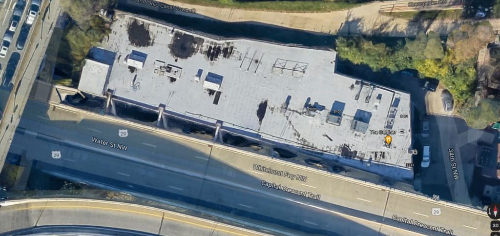
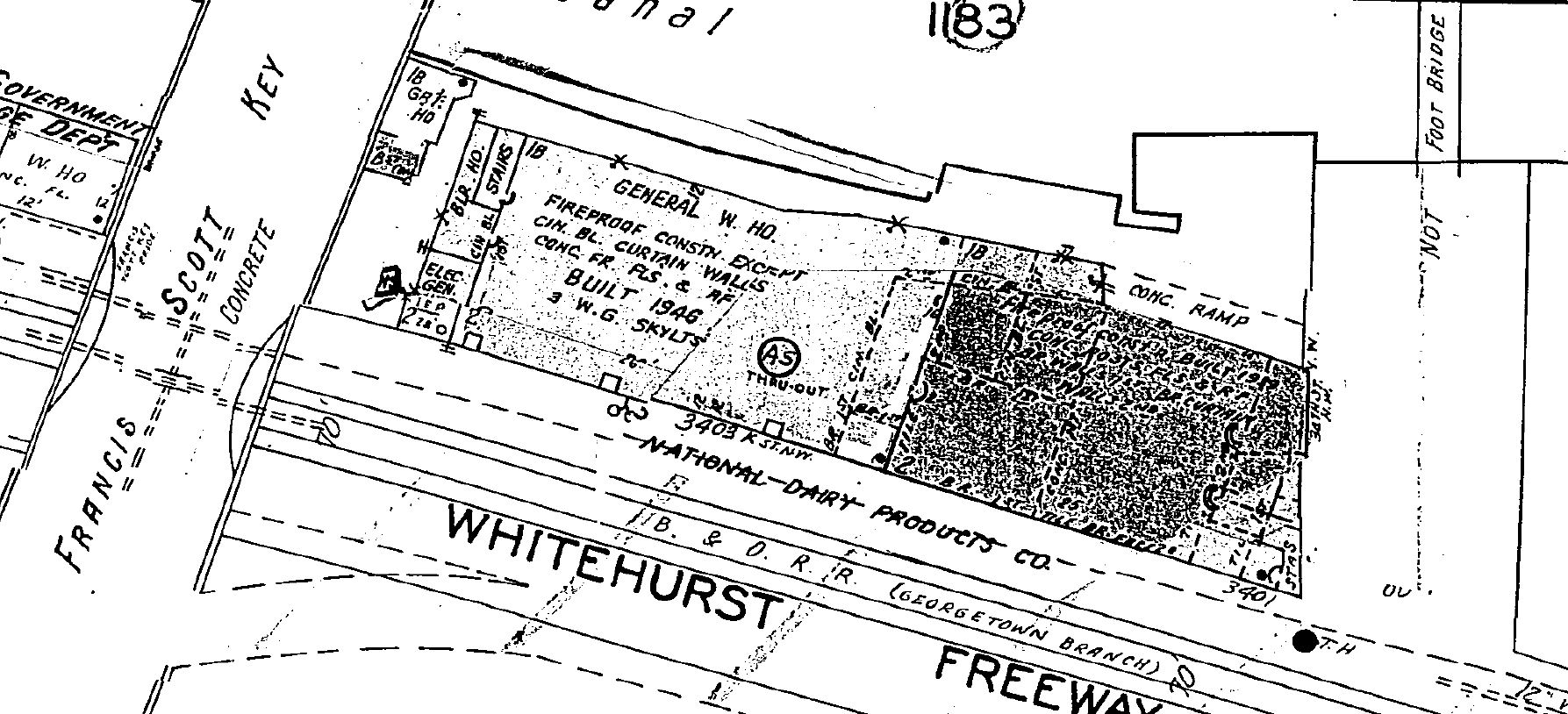
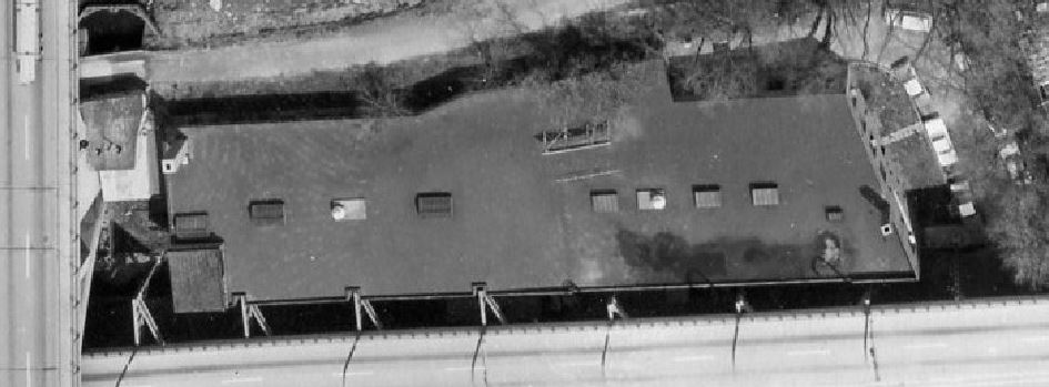
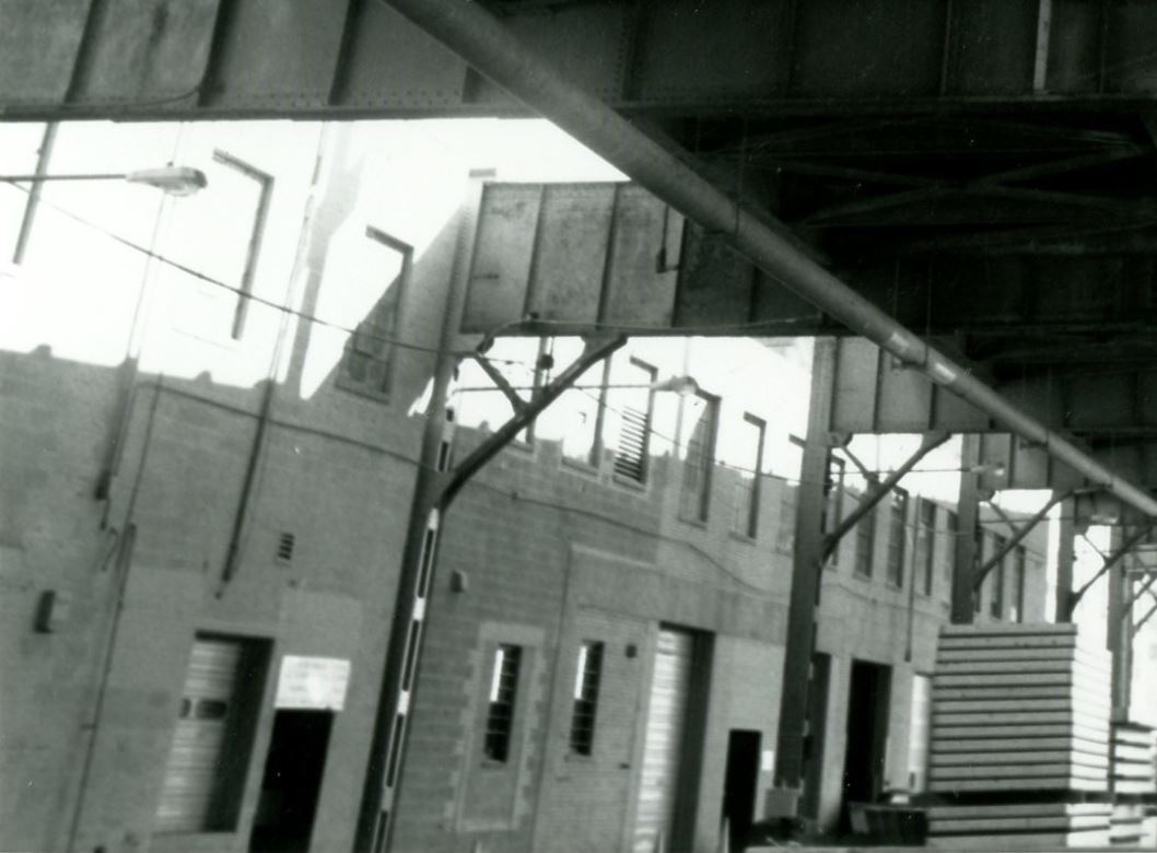
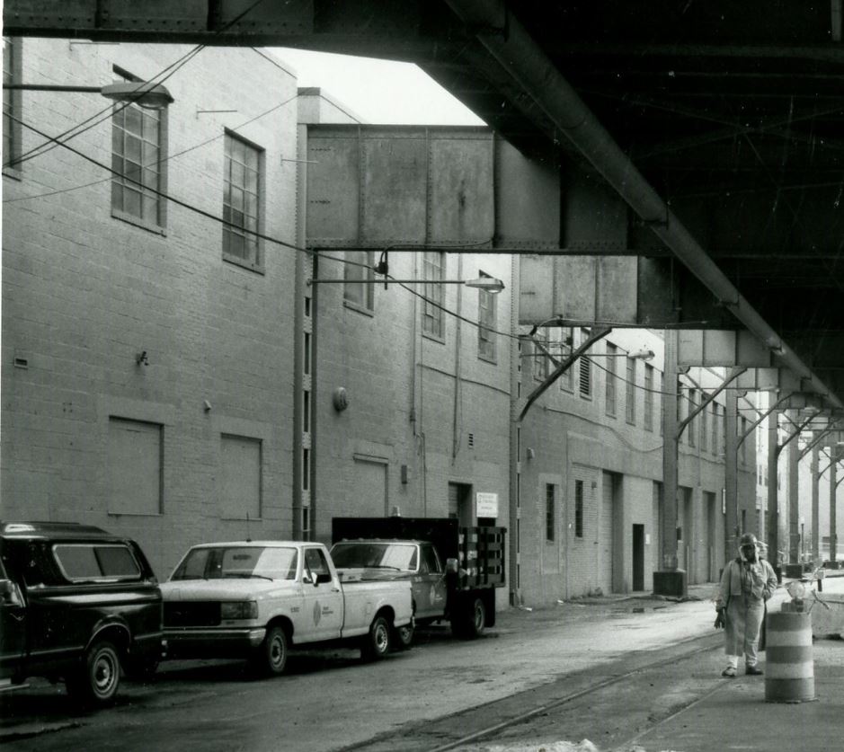
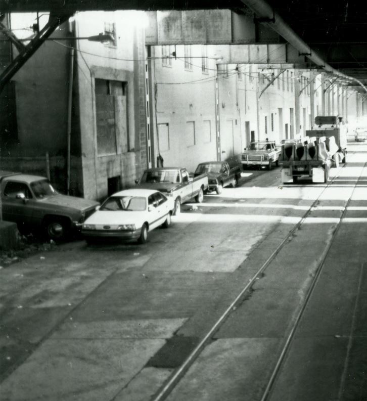
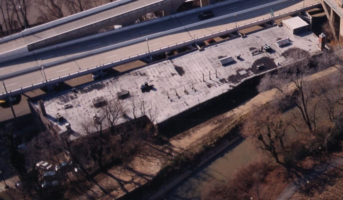
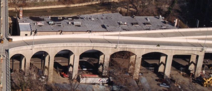
3400 K St., Google Maps, Dec 2021. Note how the three supports for the Whitehurst Freeway extend out and into the wall of the structure. This is where a 4-car siding was located on the Georgetown Branch.
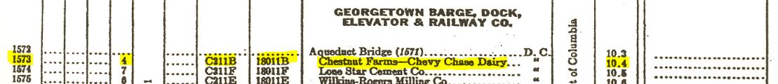
Something that has been a bit of a conundrum for me over the years is what type of business, exactly, was located at 3400 K St during my modeling era, 1945-55 and what exactly the structure looked like. On the 1954 B&O Form 6 (which describes rail customers, siding lengths, freight agents, locations, etc.) it reads “Chestnut Farms-Chevy Chase Dairy”, 4-car length, milepost 10.4. The siding does not appear on the 1941 Form 6.
1954 B&O Form 6 excerptJune 1963, B&O RR Track chart with proposed Potomac River Freeway shows the siding at 3400 K St.
Maps have varying names listed for the industry located at 3400 K St.:
1888 Sanborn: vacant flour mill & coal house
1903 Sanborn: Crystal Plate Ice Co. & vacant
1919 B&O map: no name, just “2 Story Brick“
1921 Baist: American Ice House
1928 Sanborn: Crystal Plate Ice Co.
1954 B&O Form 6: Chestnut Farms-Chevy Chase Dairy
1959 Sanborn: National Dairy Products Co.
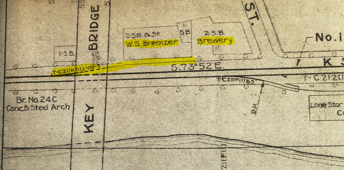
1963 B&O map: W.S. Brenizer and “Brewery” (I suspect it was The Guggenheim Co.)
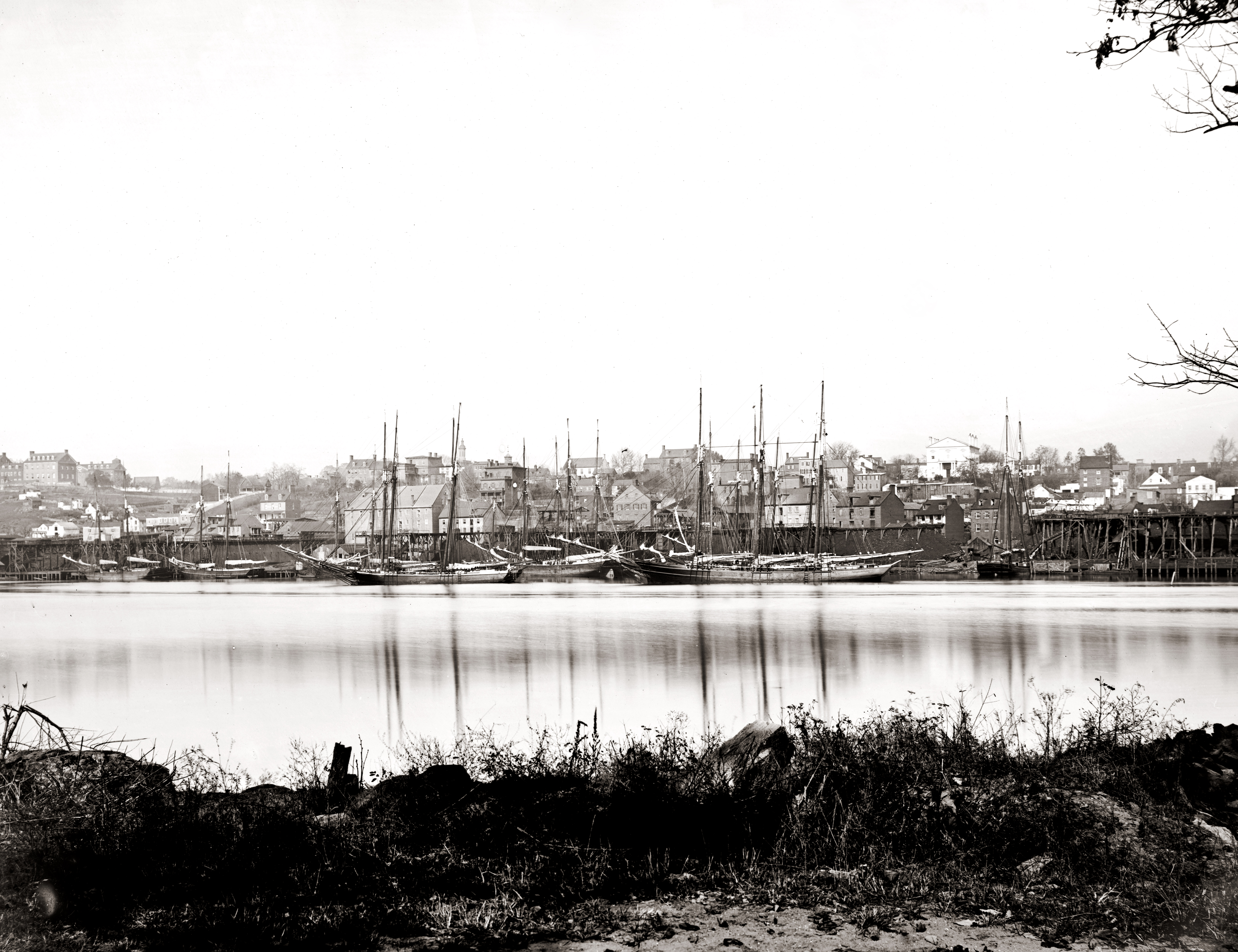
I decided to go back through photos and maps I have in my files to see if I can get an idea of what type of structure existed at this spot over the years. I’m starting way back, long before the railroad came to town because I think the history and background is pretty special. The first image comes from the year the Civil War ended. Georgetown looked pretty different back then than it does now.
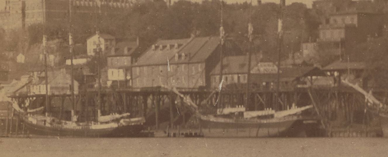
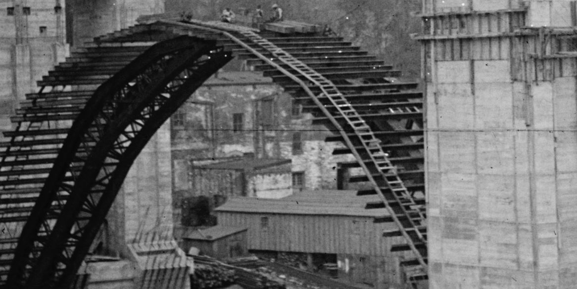
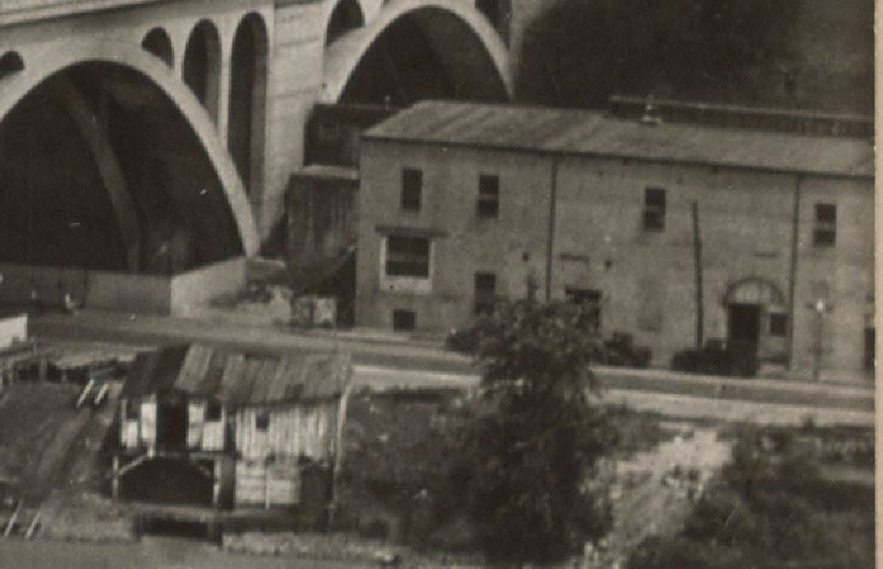
The waterfront in 1865. An image from the Georgetown Metropolitan website. I believe the 3400 block of K St is where that very large four-story warehouse is located, about a third of the way from the left. The Washington Aqueduct bridge is visible on the very far left side. Georgetown Univ. is also visible, top left. Sept 28, 1886. Another view showing some waterfront detail. A few years after the previous photo and the “coal house” structure has a large sign painted on its end. DC Historic Society, Potomac Boat Club collection. http://hdl.handle.net/1961/dcplislandora:29620
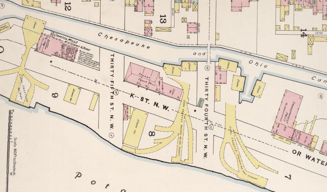
First map reference is a snip from an 1888 Sanborn Map. Note the 3400 K St. location is occupied by a Vacant Flour Mill and a Coal House, visible in the photos above. Also note the prominent overhead coal trestles which were used to transload coal from canal barges on the C&O Canal to ships docked on the Potomac River wharves.
(1888) Sanborn Fire Insurance Map from Washington, District of Columbia, District of Columbia. Sanborn Map Company. [Map] Retrieved from the Library of Congress, https://www.loc.gov/item/sanborn01227_001/.
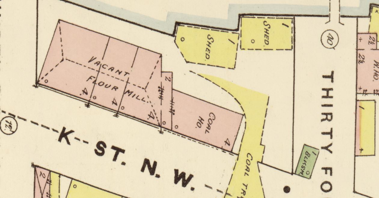
And here is a detail from the above map:
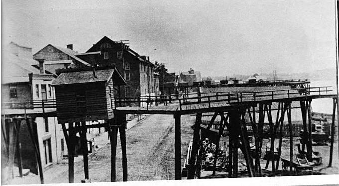
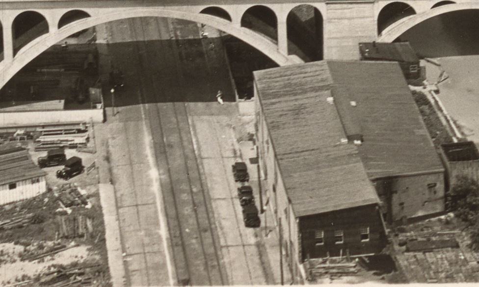
1888 Sanborn Map, LoC.View down K St, ca 1890. I believe the large mill building in the center occupied the 3400 K St. location. This is an excellent view of the overhead coal trestles. Note what looks like tracks visible in the pavement below. Image from Old Washington, D.C. in Early Photographs, 1846-1932, By: Robert Reed, 0486238695, 1980.
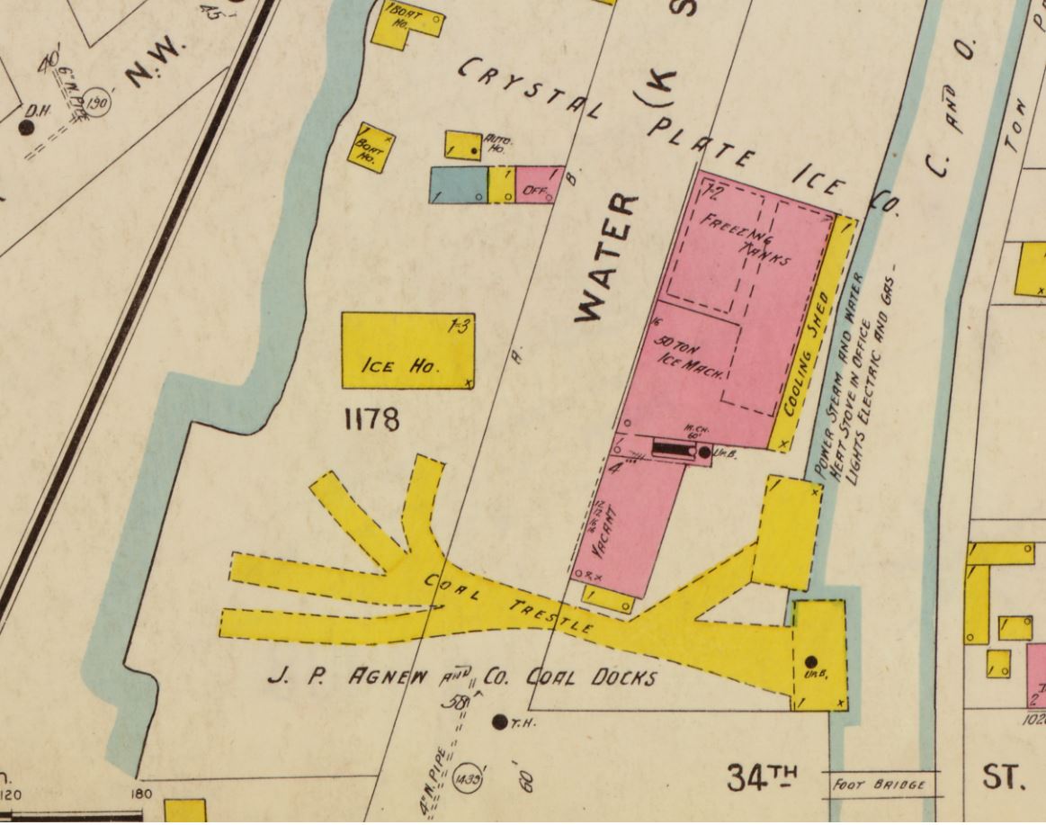
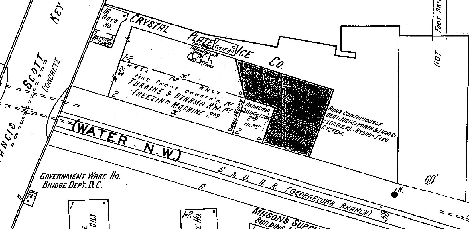
Here is a clip from a Sanborn Map from ca. 1903. Remember this pre-dates the arrival of the B&O (1910), but the Georgetown Barge Dock and Elevated Ry. Co. had been incorporated in 1889.
(1903) Sanborn Fire Insurance Map from Washington, District of Columbia, District of Columbia. Sanborn Map Company, – 1916 Vol. 1. [Map] Retrieved from the Library of Congress, https://www.loc.gov/item/sanborn01227_002/.
The business is listed as Crystal Plate Ice Co. Within the warehouse are “Freezing Tanks” and “50 Ton Ice Machinery” and an attached “Cooling Shed.”
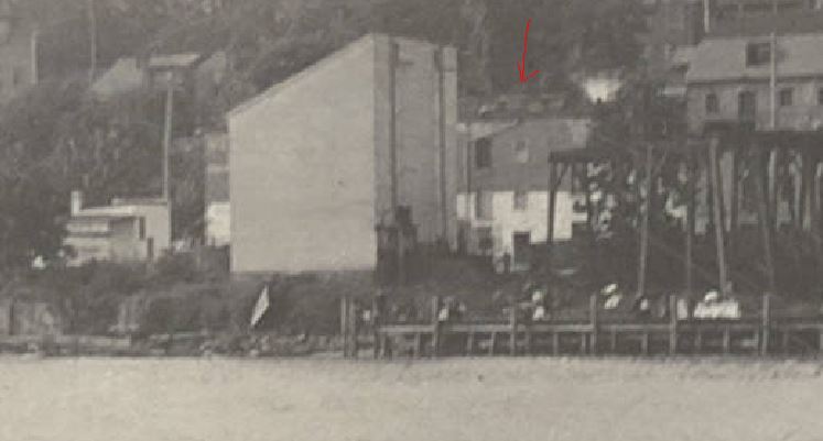
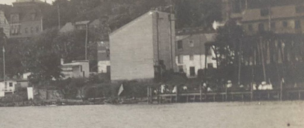
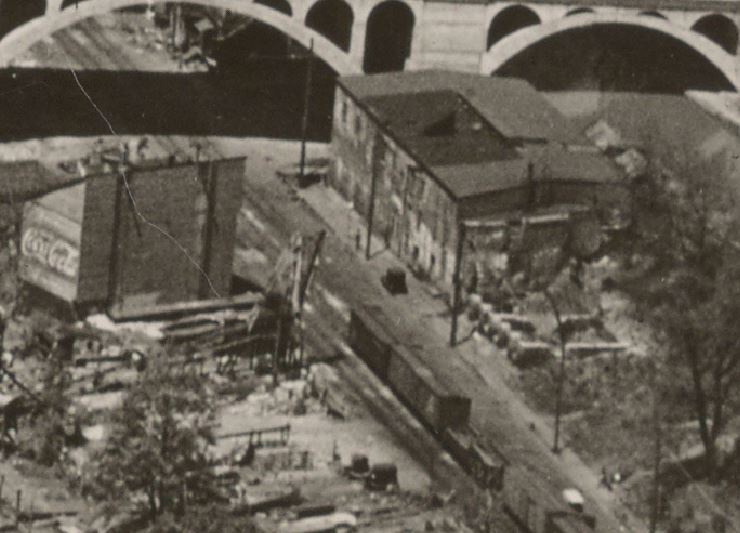
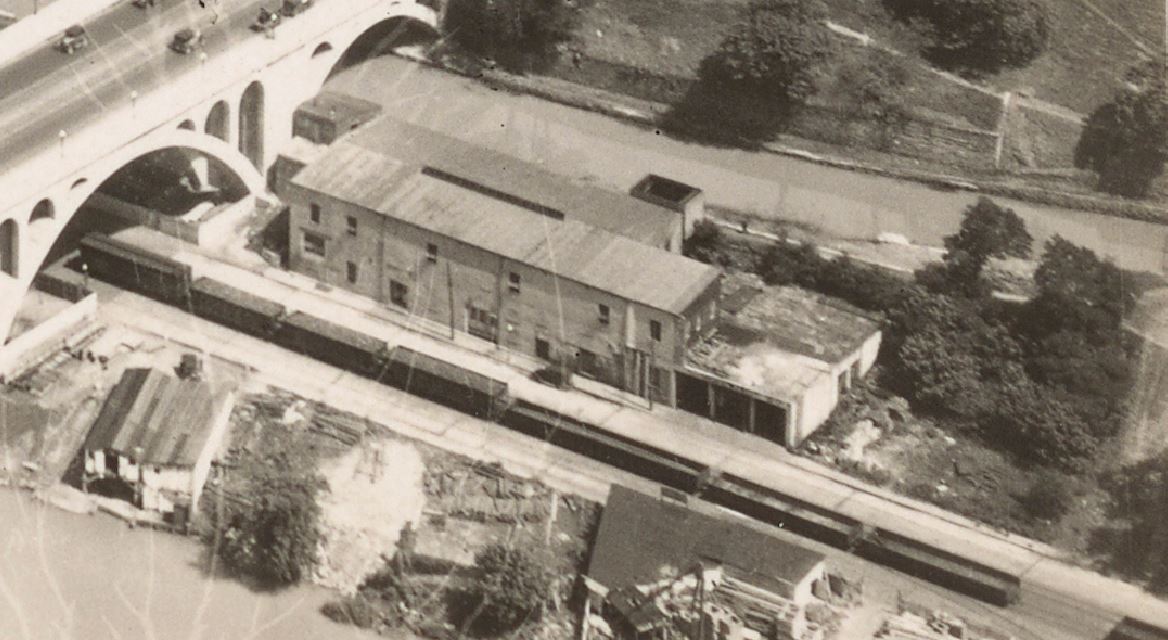
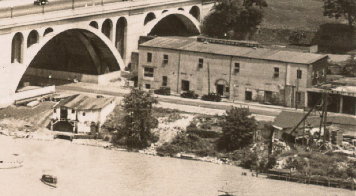
August 14, 1904. Note the presence of the tall coal trestles extending to the wharves. DC Historic Society, Potomac Boat Club collection. http://hdl.handle.net/1961/dcplislandora:29662 August 14, 1904. Another nearly identical view from the same collection. DC Historic Society, Potomac Boat Club collection. http://hdl.handle.net/1961/dcplislandora:29660 A few years later, 3400 K St, ca 1911-18. HABS collection. https://www.loc.gov/pictures/item/dc0048.photos.025822p/ (1920) Key Bridge under const. United States Washington D.C. District of Columbia Washington D.C, 1920. [Photograph] Retrieved from the Library of Congress, https://www.loc.gov/item/2016826863/. 1921, “Airscapes” of American and Foreign Areas, 1917 – 1964, National Archives https://catalog.archives.gov/id/68144007 Note the “coal house” structure to the right has been razed. Ca. 1920s, “Airscapes” of American and Foreign Areas, 1917 – 1964, National Archives https://catalog.archives.gov/id/68144007 Aug, 1927, “Airscapes” of American and Foreign Areas, 1917 – 1964, National Archives https://catalog.archives.gov/id/68144007 Ca. 1920s. A view from the other direction. “Airscapes” of American and Foreign Areas, 1917 – 1964, National Archives https://catalog.archives.gov/id/68144007 1928 Sanborn Map.
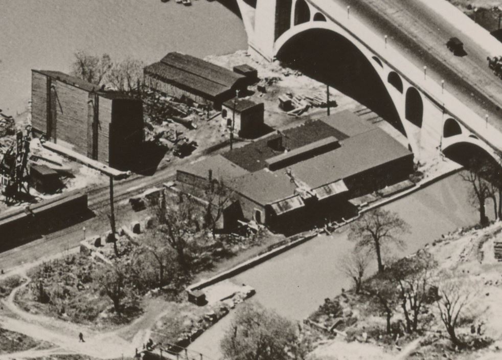
A photo by Theodor Horydczak shows the site ca 1920s, likely the late 20s. Note that the building appears to have been either been razed, rebuilt or heavily renovated and the Key Bridge is now complete.
Horydczak, T., photographer. Lone Star Cement Co. Lone Star Cement Co. and negative of adjacent property. Washington D.C, None. ca. 1920-ca. 1950. [Photograph] Retrieved from the Library of Congress, https://www.loc.gov/item/2019673071/. 1931. “Airscapes” of American and Foreign Areas, 1917 – 1964, National Archives https://catalog.archives.gov/id/68144007 June, 1931. “Airscapes” of American and Foreign Areas, 1917 – 1964, National Archives https://catalog.archives.gov/id/68144007 July 1931, “Airscapes” of American and Foreign Areas, 1917 – 1964, National Archives https://catalog.archives.gov/id/68144007 July 1931, “Airscapes” of American and Foreign Areas, 1917 – 1964, National Archives https://catalog.archives.gov/id/68144007 A view down K St. October 28, 1936, from the Barriger Collection. https://www.flickr.com/photos/barrigerlibrary/12230291546/Harris & Ewing, photographer. (1930) Train tracks near Potomac River, Washington, D.C. United States Washington D.C. District of Columbia Washington D.C, 1930. [April] [Photograph] Retrieved from the Library of Congress, https://www.loc.gov/item/2016889645/.
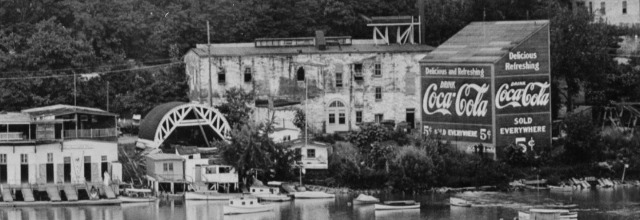
It appears that in the 1940s an addition was made on the east end of the block. I believe sections of the older structure (from the 1920s era) remain, but it seems that some of the structures were replaced.
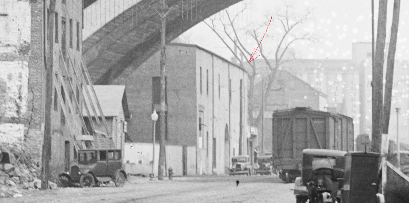
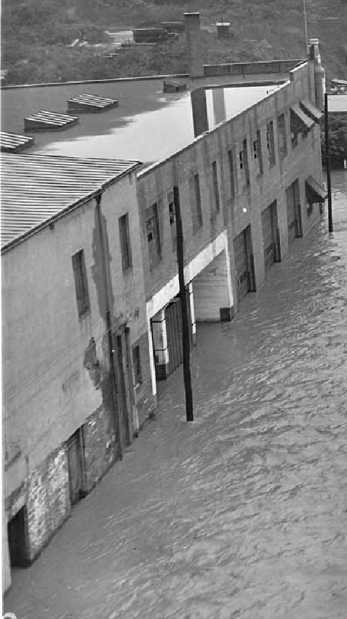
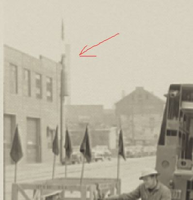
Note the large “bottle” sign at the top right corner of the building, facing away from the photographer. A neat detail. If only I could see the front of it! Oct 17, 1942, 3400 K St. – flooding. Credit: Acme Photo. eBay purchase, personal collection. A promotional photo by Theodore Horydczak captured a portion of the “new” structure, with the bottle sign clearly visible. Horydczak, T., photographer. Potomac Electric Power Co. miscellaneous. Manhole crew and truck I. Washington D.C, None. ca. 1920-ca. 1950. [Photograph] Retrieved from the Library of Congress, https://www.loc.gov/item/2019672478/.
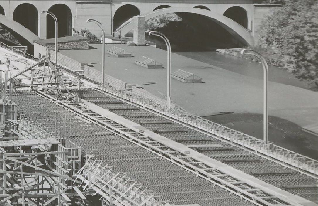
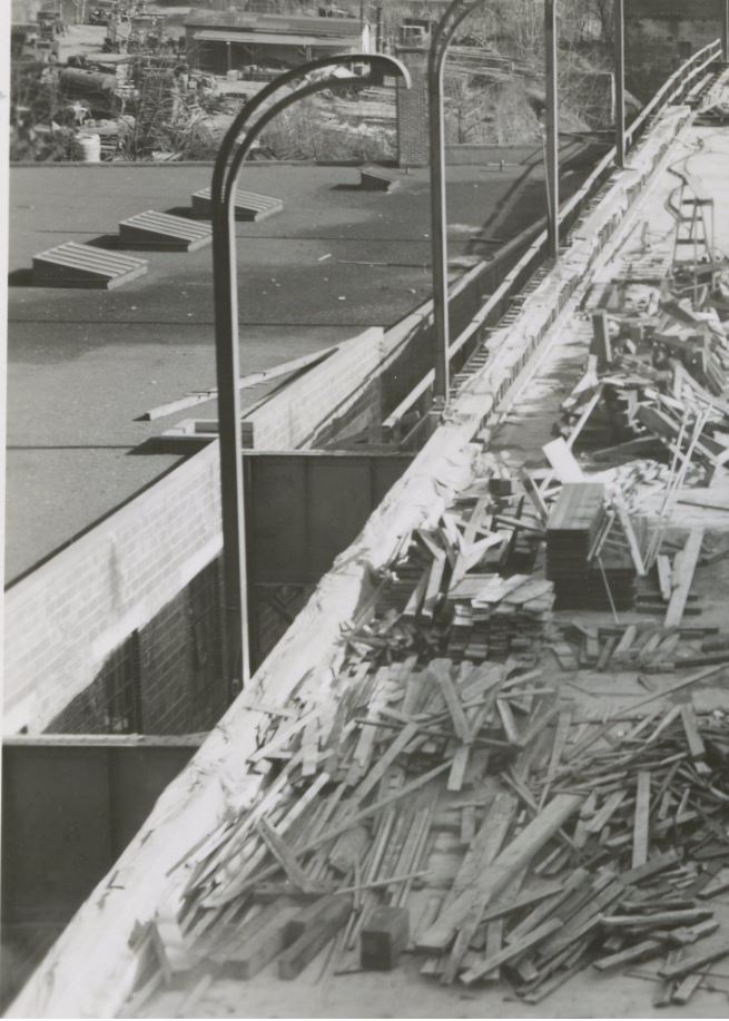
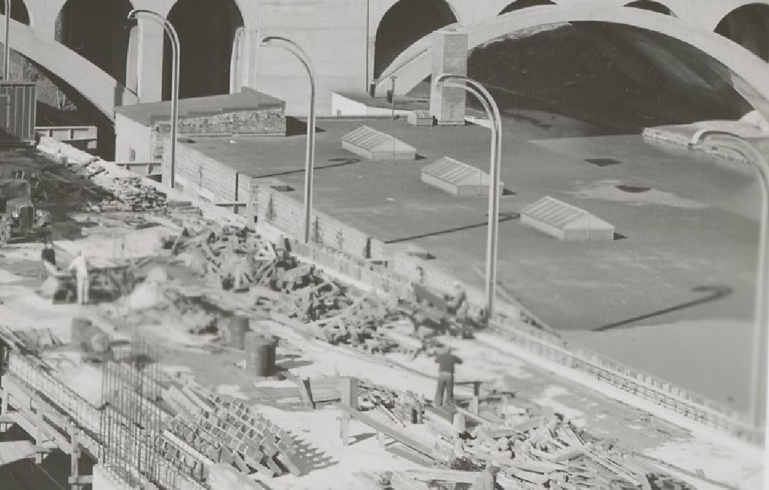
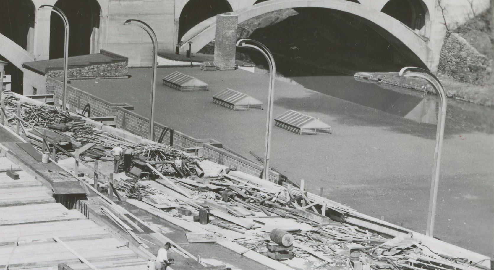
It is likely the structure was changed when the Whitehurst Freeway was being constructed, ca 1946:
1958 Sanborn Map. Note that the structure now reads “Built 1946”. I suspect that in the mid-40s, or perhaps when the Whitehurst was being built in 1947, the old structure was razed and a new on built in its place to accommodate the new freeway structure. 1948. Whitehurst Freeway construction showing the roof of the new 3400 K St. structure. https://ddotlibrary.omeka.net/ 1948. Whitehurst Freeway construction showing the roof of the new 3400 K St. structure. https://ddotlibrary.omeka.net/ 1948. Whitehurst Freeway construction showing the roof of the new 3400 K St. structure. https://ddotlibrary.omeka.net/ 1948. Whitehurst Freeway construction showing the roof of the new 3400 K St. structure. https://ddotlibrary.omeka.net/ 1963, DDOT DC.1972, Hurricane Agnes. DDOT DC. 1972, Hurricane Agnes. DDOT DC. 1991, DDOT DC 1991, DDOT DC 1991, DDOT DC 1991, DDOT DC 1997, DDOT DC1997, DDOT DC
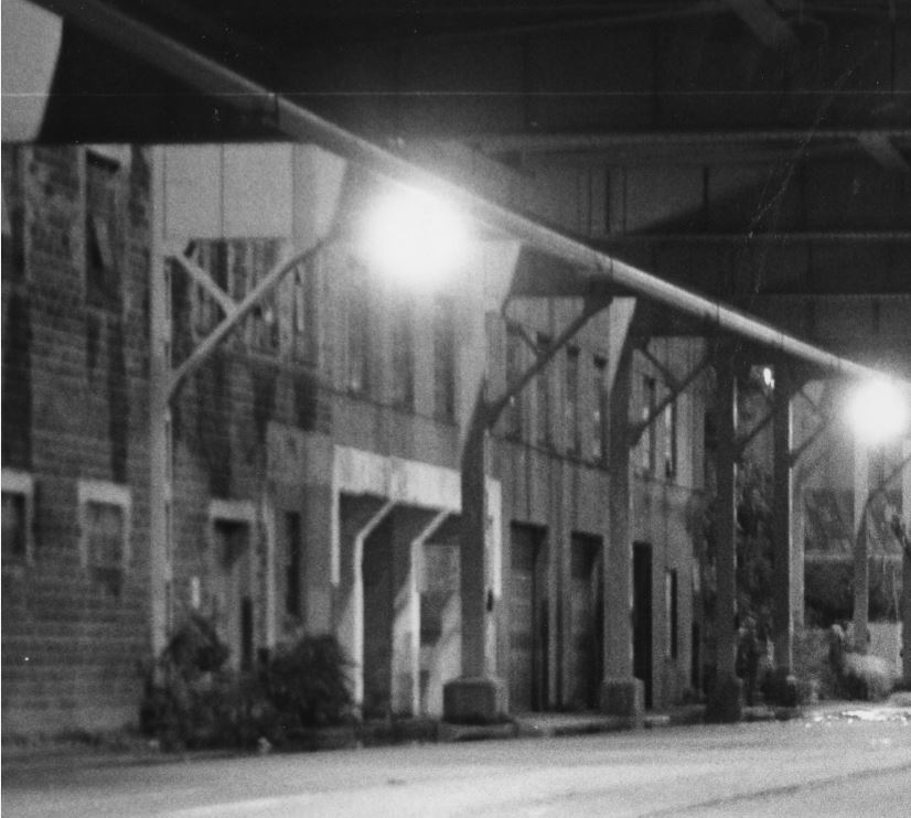
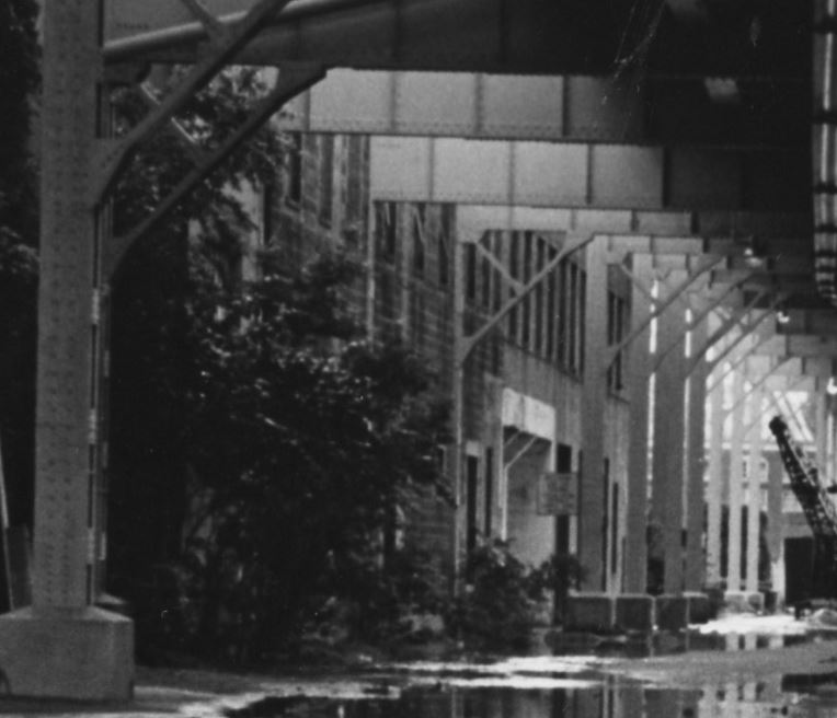
I hope you enjoyed this photo tour of the 3400 K St. location. I commuted from Bethesda to Rosslyn by bicycle for a few years and every morning and evening I walked up and down 34th St past this location from K St to the bridge over the C&O Canal and on up and over Key Bridge. Often I would ponder the history of the building and what came before. When I was commuting, it was a fitness center / gym and various professional offices. No doubt more research is in order to get more details on the businesses that operated here, but this is a good start. When I have more information, I will post an update.
Ray Mumford captured this wet, foggy scene from the cab in 1959 as the Georgetown turn is about to cross Bradley Blvd. on its way into Bethesda, visible in the distance.
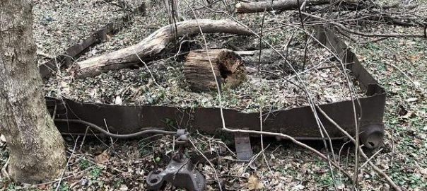
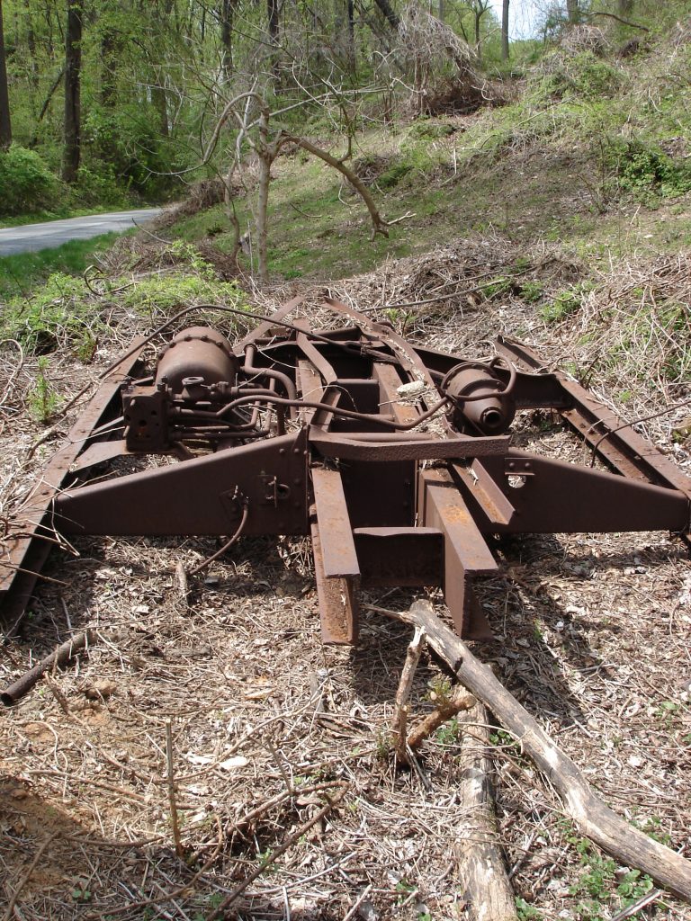
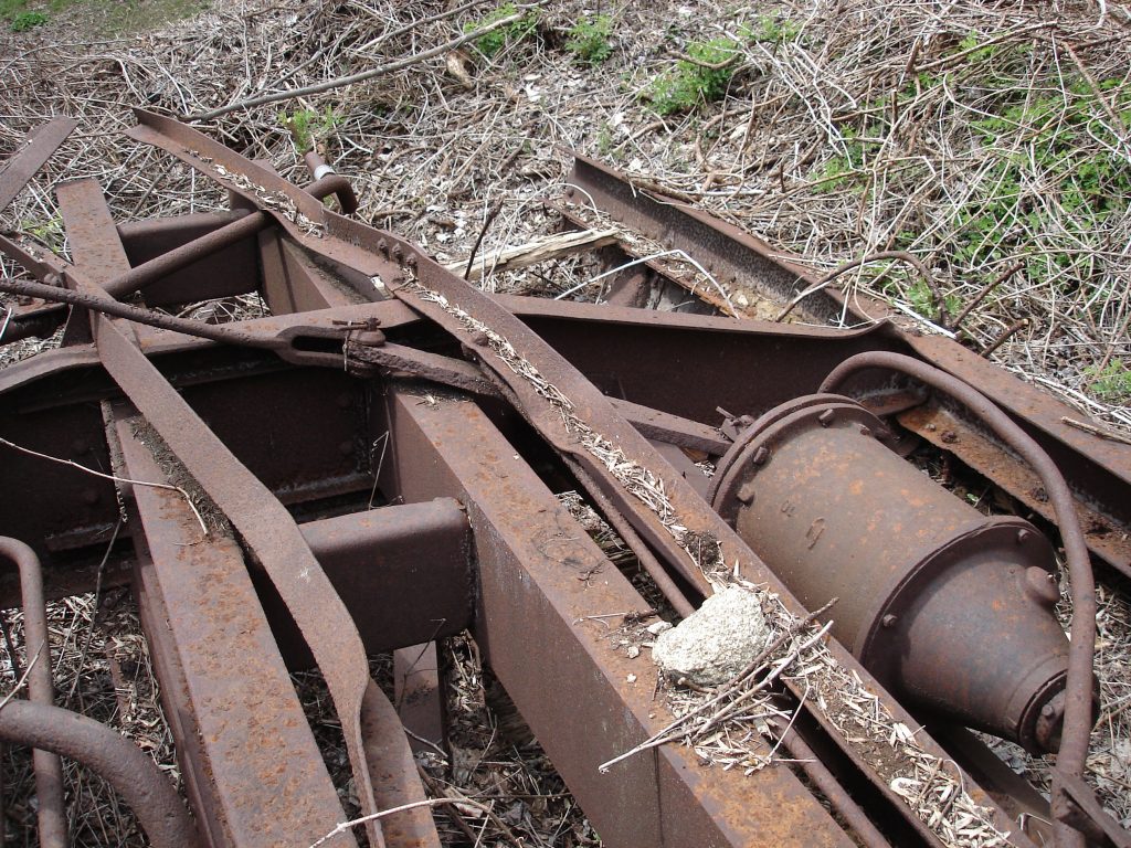
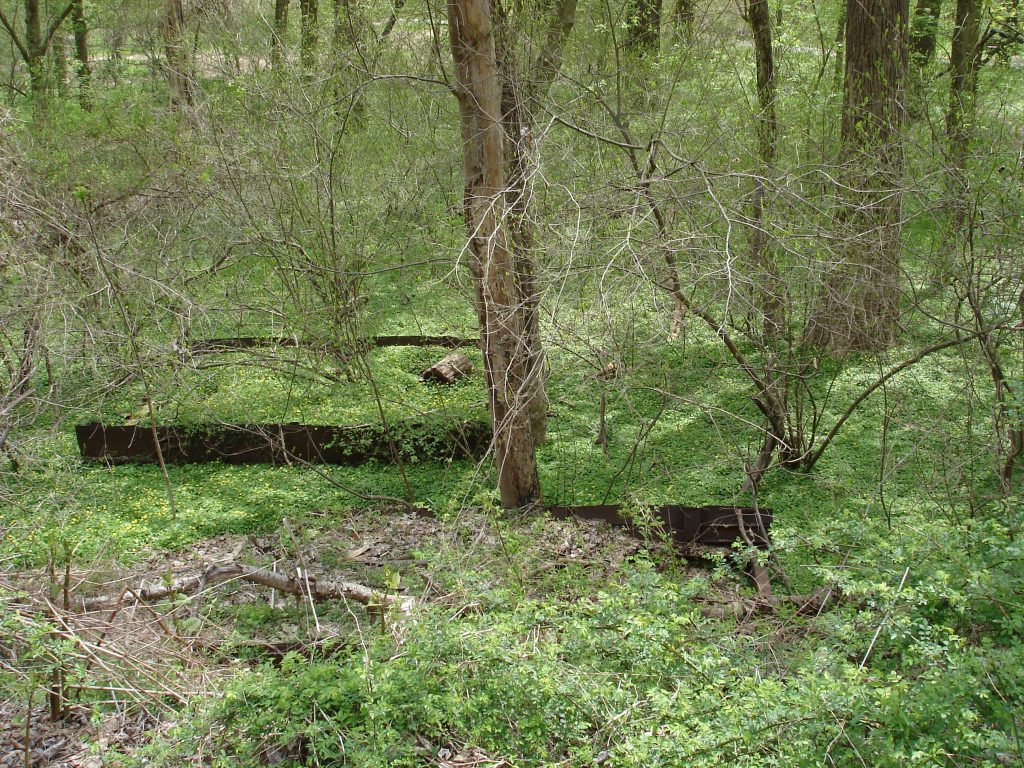
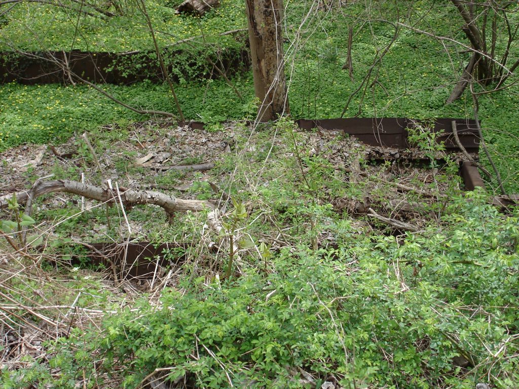
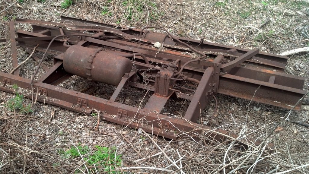
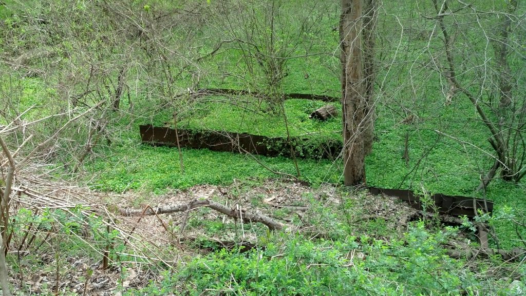
As some of you may or may not know, there are remains of a wrecked boxcar located on the Georgetown Branch just a bit north of the Dalecarlia tunnel. The wreckage has been somewhat of a mystery as to how it happened, where the car came from and why it was partially scrapped in place. I first got wind of this discovery in 2014 when some photos were shared online:
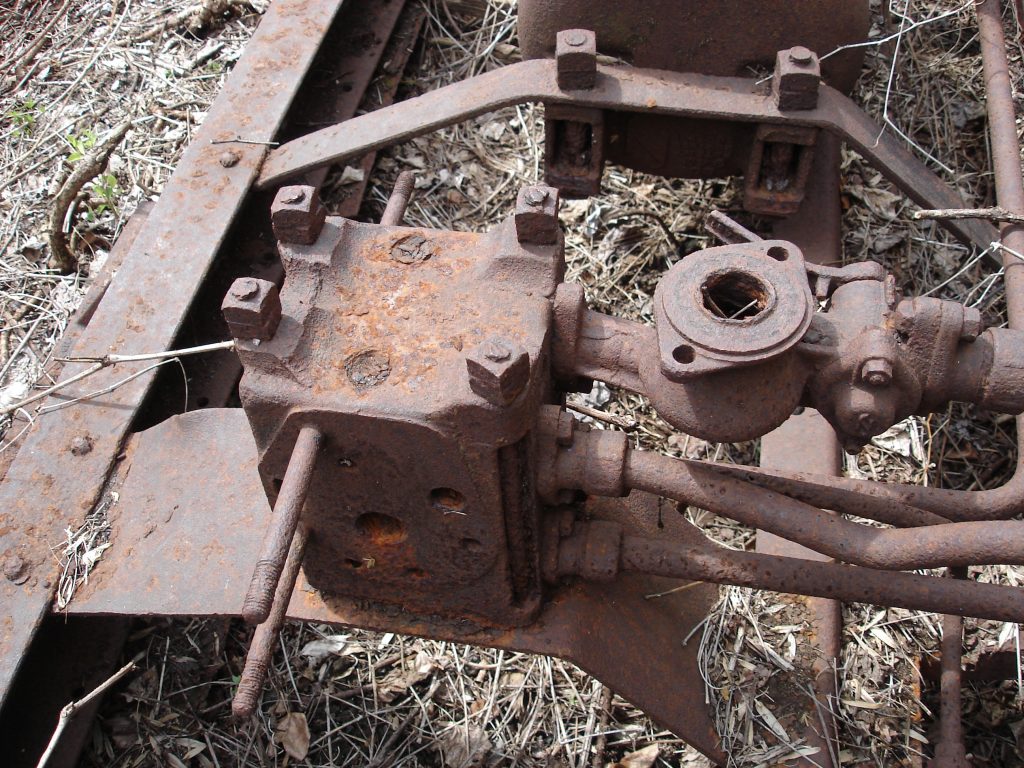
The underframe center section sat further in the woods and was dragged closer to the right of way during a cleanup event by locals. Lots of folks (including myself) developed theories on just how the car came to be where it lay. In 2019 I visited the site with my friend Kelly and snapped many photos of the wreck. This past Fall I circled back on my notes and spent some serious time studying the photos I had taken and correlating details on the wrecked car with photos of other steam era freight cars. My goal was to hone in on what type of car it is and where it may have came from. I created a presentation (which you can download below!) that outlines my findings. The TL:DR is that I believe it’s a B&O class M-26 (X-29) boxcar that was wrecked in the flood of 1942 near Fletcher’s Boathouse. The car was likely loaded on a flatcar, useful sections scrapped from the car and the flood-mangled carcass tossed by the wayside in an area away from the National Park land (C&O Canal) which is where it rests today.
I hope you enjoy my journey to solve this riddle and I welcome any and all questions or comments. If you think there’s something I may have missed or got wrong, it would be great to hear from you! I am not an expert in freight cars, but over the last few years have taken a major interest in studying steam era freight cars and prototype modeling. (I now own a couple ORERs and various other reference books which are wonderful resources!) Please have a look at the presentation and leave your comments below!